Approved by and published under the authority of the Secretary General
INTERNATIONAL CIVIL AVIATION ORGANIZATION
Doc 9303
Machine Readable Travel Documents
Part 7: Machine Readable Visas
Eighth Edition, 2021

Approved by and published under the authority of the Secretary General
INTERNATIONAL CIVIL AVIATION ORGANIZATION
Doc 9303
Machine Readable Travel Documents
Part 7: Machine Readable Visas
Eighth Edition, 2021

Published in separate English, Arabic, Chinese, French, Russian
and Spanish editions by the
INTERNATIONAL CIVIL AVIATION ORGANIZATION
999 Robert-Bourassa Boulevard, Montréal, Quebec, Canada H3C 5H7
Downloads and additional information are available at www.icao.int/security/mrtd
Doc 9303, Machine Readable Travel Documents
Part 7 — Machine Readable Visas
Order No.: 9303P7
ISBN 978-92-9265-364-4 (print version)
ISBN 978-92-9275-310-8 (electronic version)
© ICAO 2021
All rights reserved. No part of this publication may be reproduced, stored in a
retrieval system or transmitted in any form or by any means, without prior
permission in writing from the International Civil Aviation Organization.
(iii)
AMENDMENTS
Amendments are announced in the supplements to the Products and Services
Catalogue; the Catalogue and its supplements are available on the ICAO
website at www.icao.int. The space below is provided to keep a record of such
amendments.
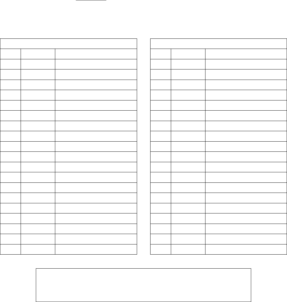
RECORD OF AMENDMENTS AND CORRIGENDA
AMENDMENTS
CORRIGENDA
No.
Date
Entered by
No.
Date
Entered by
1
20/3/24
ICAO
The designations employed and the presentation of the material in this publication do not
imply the expression of any opinion whatsoever on the part of ICAO concerning the legal
status of any country, territory, city or area or of its authorities, or concerning the
delimitation of its frontiers or boundaries.
(v)
TABLE OF CONTENTS
1. SCOPE .............................................................................................................................................. 1
2. TECHNICAL SPECIFICATIONS FOR FORMAT-A MACHINE READABLE VISAS (MRV-A) .......... 1
2.1 Dimensions and Placement of the MRV-A ............................................................................ 1
3. GENERAL LAYOUT OF THE MRV-A ................................................................................................ 3
3.1 MRV-A Zones ....................................................................................................................... 3
3.2 Content, Use and Dimensional Flexibility of Zones............................................................... 3
3.3 Dimensional Flexibility of Zones I to V .................................................................................. 4
4. DETAILED LAYOUT OF THE MRV-A ............................................................................................... 5
4.1 Visual Inspection Zone (VIZ) (Zones I-V) .............................................................................. 5
4.2 Machine Readable Zone (MRZ) (Mandatory Zone VII) ......................................................... 8
4.3 Portrait .................................................................................................................................. 14
4.4 MRV-A Diagrams .................................................................................................................. 15
5. TECHNICAL SPECIFICATIONS FOR FORMAT-B MACHINE READABLE VISAS (MRV-B) .......... 19
5.1 Dimensions and Placement of the MRV-B ............................................................................ 19
6. GENERAL LAYOUT OF THE MRV-B ................................................................................................ 20
6.1 MRV-B Zones ....................................................................................................................... 20
6.2 Content, Use and Dimensional Flexibility of Zones............................................................... 21
6.3 Dimensional Flexibility of Zones I to V .................................................................................. 21
7. DETAILED LAYOUT OF THE MRV-B ............................................................................................... 22
7.1 Visual Inspection Zone (VIZ) (Zones I-V) .............................................................................. 22
7.2 Machine Readable Zone (MRZ) (Mandatory Zone VII) ......................................................... 25
7.3 Portrait .................................................................................................................................. 32
7.4 MRV-B Diagrams .................................................................................................................. 33
8. USE OF OPTIONAL BARCODES ON MACHINE READABLE VISAS ............................................. 37
8.1 Scope ................................................................................................................................... 37
8.2 Definition ............................................................................................................................... 37
8.3 Location of Bar Code(s) ........................................................................................................ 37
8.4 Quality of Bar Code(s) .......................................................................................................... 38
8.5 Symbologies and Logical Data Structure .............................................................................. 38
8.6 Machine Reading of the Bar Code(s).................................................................................... 38

(vi) Machine Readable Travel Documents
Page
9. USE OF OPTIONAL DIGITAL SEALS FOR VISA DOCUMENTS
9.1 Content and Encoding Rules………………………………………………………………………. 39
9.2 Visa Signer and Seal Creation…………………………………………………………………….. 42
9.3 Public Key Infrastructure (PKI) and Certificate Profiles…………………………………………. 42
9.4 Validation Policy Rules (Informative)……………………………………………………………… 42
10. REFERENCES (NORMATIVE) ........................................................................................................... 43
APPENDIX A TO PART 7. EXAMPLES OF PERSONALIZED MRVs (INFORMATIVE) ......................... App A-1
A.1 MRV-A Examples ................................................................................................................. App A-1
A.2 MRV-B Examples ................................................................................................................. App A-3
APPENDIX B TO PART 7. CONSTRUCTION OF THE MRZ (INFORMATIVE) ....................................... App B-1
B.1 MRV-A MRZ Construction .................................................................................................... App B-1
B.2 MRV-B MRZ Construction .................................................................................................... App B-2
APPENDIX C TO PART 7. POSITIONING IN PASSPORT (INFORMATIVE) .......................................... App C-1
C.1 MRV-A Positioning ................................................................................................................ App C-1
C.2 MRV-B Positioning ................................................................................................................ App C-2
APPENDIX D TO PART 7. MATERIALS AND PRODUCTION METHODS (INFORMATIVE) ................. App D-1
APPENDIX E TO PART 7. WORKED EXAMPLE VISIBLE DIGITAL SEAL
FOR VISA DOCUMENT (INFORMATIVE) ............................................................................................ App E-1
______________________
1
1. SCOPE
Part 7 defines the specifications for machine readable visas (MRV) which allow compatibility and global interchange
using both visual (eye readable) and machine readable means. The specifications lay down standards for visas which
can, where issued by a State and accepted by a receiving State, be used for travel purposes. The MRV shall, as a
minimum, contain the data specified herein in a form that is legible both visually and by optical character recognition
methods, as presented herein. Part 7 contains specifications for both Format-A and Format-B types of visas.
Part 7 shall be read in conjunction with:
• Part 1 — Introduction;
• Part 2 — Specifications for the Security of the Design, Manufacture and Issuance of MRTDs;
• Part 3 — Specifications Common to all MRTDs; and
• Part 13 — Visible Digital Seals.
2. TECHNICAL SPECIFICATIONS FOR FORMAT-A
MACHINE READABLE VISAS (MRV-A)
This section defines those specifications which are unique to Format-A machine readable visas (MRV-A) and are
necessary for global interoperability. Specifications are included for the discretionary expansion of the machine readable
data capacity of the MRV beyond that defined for global interoperability. The MRV-A is suitable for use by States that
wish to have maximum space available to accommodate their data requirements and that do not need to maintain a
clear area on the passport visa page adjacent to the visa.
2.1 Dimensions and Placement of the MRV-A
The dimensions and placement of the MRV-A shall be as follows:
MRV-A nominal dimensions. The nominal dimensions of the MRV-A shall be as follows:
80.0 mm × 120.0 mm (3.15 in × 4.72 in)
MRV-A margins. The dimensional specifications refer to the outer limits of the MRV-A. A margin of 2.0 mm (0.08 in)
along each outer edge, with the exception of the header zone, must be left clear of data.
2 Machine Readable Travel Documents
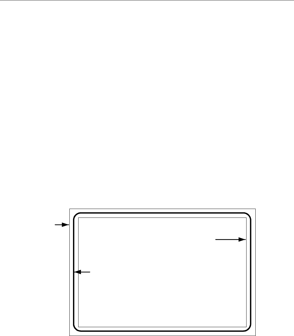
MRV-A edge tolerances. The edges of the MRV-A shall be within the area circumscribed by the concentric rectangles as
illustrated in Figure 1.
Inner rectangle: 79.0 mm × 119.0 mm (3.11 in × 4.69 in)
Outer rectangle: 81.0 mm × 121.0 mm (3.19 in × 4.76 in)
MRV-A thickness. If the visa is issued as a label, the increase in thickness once the label is attached to the passport visa
page shall not exceed 0.19 mm (0.0075 in). The thickness of the area within the machine readable zone (MRZ) shall not
vary by more than 0.05 mm (0.002 in). If a protective laminate is used, it is recommended that its thickness not exceed
0.15 mm (0.006 in).
General note.— The decimal notation used in these specifications conforms to ICAO practice. This differs
from ISO practice where a decimal point (.) in imperial measurements and a comma (,) in metric measurements are
used.
Placement of the MRV-A. The MRV-A shall be positioned as follows:
The MRV-A shall be located on the passport visa page such that the MRZ is coincident with and parallel to the outside
edge (reference edge) of the passport visa page, and the left edge of the MRV-A is coincident with and parallel to the left
edge of the passport visa page as defined in Appendix C, Section C.1.
The MRZ shall be located such that the two OCR lines contained therein are within the Effective Reading Zone (ERZ) as
defined in Doc 9303-3.
Only one MRV-A shall be located on a passport visa page (see Appendix C, Section C.1).
Figure 1. MRV-A dimensional illustration
Not to scale
Outer
rectangle
Inner
rectangle
Outer edge
of MRV-A

Part 7. Machine Readable Visas 3
3. GENERAL LAYOUT OF THE MRV-A
The MRV-A follows a standardized layout to facilitate reading of data globally, by visual and machine readable means, to
accommodate the various requirements of States’ laws and practices and to achieve the maximum standardization
within those divergent requirements.
The standard layout incorporates space for a portrait of the holder and other identification feature(s). The inclusion of a
portrait on a visa is strongly recommended in the interests of security, but States who are not yet able to apply portraits
may fill this space with, for example, a national crest.
3.1 MRV-A Zones
An MRV-A is divided into six zones as follows:
Zone I Mandatory header
Zone II Mandatory and optional personal data elements
Zone III Mandatory and optional document data elements
Zone IV Signature (original or reproduction) or authentication
Zone V Mandatory zone for identification feature (feature optional)
Zone VII Mandatory machine readable zone (MRZ)
Note 1.— The signature in Zone IV of a visa is that of an issuing officer, not of the document holder. The
signature may be replaced or accompanied by an official stamp.
Note 2.— To facilitate inspection of visas at border control, the layout of the visa presents Zone III above
Zone II.
Note 3.— Zone VI is not available on an MRV issued in the form of a label.
Note 4.— Zones I to V constitute the Visual Inspection Zone (VIZ).
Zones I and VII are mandatory. Certain data in Zones II and III are also mandatory. The mandatory components of these
four Zones represent the minimum data requirements for an MRV-A. The optional data elements in Zones II, III and V
and in optional Zone IV may be utilized to accommodate the diverse requirements of States, while achieving the desired
level of standardization. The data elements which may be included in the various zones and their order are set out in
Section 4.4. Section 4.4 also illustrates the dimensional specifications and tolerances for the layout of the MRV-A and
the technical specifications for the printing of data elements within the zones, as well as the guidelines for positioning
and adjusting the dimensional specifications of Zones I to V to accommodate the flexibility desired by issuing States.
Examples of personalized MRV-As are shown in Appendix A, Section A.1. Appendix B, Section B.1 illustrates the format
for the presentation of the machine readable data in Zone VII.
3.2 Content, Use and Dimensional Flexibility of Zones
The data elements to be included in the zones, the treatment of the zones and guidelines for the dimensional layout of
zones shall be as described hereunder.
Zone I identifies the issuing State and the type of document. These elements are mandatory. The order of the data
elements in this zone is left to the discretion of the issuing State.

4 Machine Readable Travel Documents
To facilitate the checking of visas by airline personnel and control authorities, the essential details of the visa document
shall be entered in a standard sequence in Zone III while essential personal details of the holder shall be entered in a
standard sequence in Zone II. On a visa, Zone III appears above Zone II.
Zone IV provides space for an optional signature or authentication. This is normally the signature of the issuing officer or
an official stamp. The application of an official stamp elsewhere on the document is not precluded except that it must not
intrude into the MRZ or affect the legibility of entered data.
Zone VII conforms in height to the MRZ defined for all MRTDs so that the machine readable data lines fall within the
ERZ specified in Doc 9303-3, thus allowing a single reader to be used for all types and sizes of MRTDs.
All MRZ data elements are mandatory and shall be shown as defined in Section 4.2 even though an issuing State may
choose not to include a specific MRZ data element in the VIZ.
3.3 Dimensional Flexibility of Zones I to V
Zones I to V may be adjusted in size and shape within the overall dimensional specifications of the MRV-A to
accommodate the diverse requirements of issuing States. All zones, however, shall be bounded by straight lines, and all
angles where straight lines join shall be right angles (i.e. 90 degrees). It is recommended that the zone boundaries not
be printed on the MRV-A. The nominal position of the zones is shown in Section 4.4, Figure 4.
When an issuing State chooses to produce an MRV-A as a securely attached card containing a transparent or otherwise
unprintable border around the card, the available area within the zones will be reduced. The full MRV-A dimensions and
zone boundaries shall be measured from the outside edge of this border, which is the external edge of the MRV-A.
Zone I shall be adjacent and parallel to the top edge of the MRV-A and extend across the full 120.0 mm ± 1.0 mm
(4.72 in ± 0.04 in) dimension. The issuing State may vary the vertical dimension of Zone I, as required, but this
dimension shall be sufficient to allow legibility of the data elements in the zone, and the height shall not be greater than
12.0 mm (0.47 in) as defined in Section 4.4, Figure 4.
Zone V shall be located such that its left edge is coincident with the left edge of the MRV-A, as defined in Section 4.4,
Figure 4. Zone V may vary in size but any variation from the nominal dimensions shall not exceed the tolerances
specified in Section 4.4, Figure 4.
Zone V may move vertically along the left edge of the MRV-A and overlay a portion of Zone I as long as individual
details contained in either zone are not obscured. Zone V may, as a result, have its lower external boundary coincident
with the top edge of the MRZ of the MRV-A and its upper external boundary coincident with the top edge of the MRV-A.
The upper boundary of Zone III shall be coincident with the lower boundary of Zone I.
Zone III may extend to the full width of that portion of the MRV-A to the right of Zone V.
The lower boundary of Zone III (see Section 4.4, Figure 4) may be positioned at the discretion of the issuing State.
Enough space shall be left for Zone II and Zone IV (when used) below the boundary.
Normally, the upper boundary of Zone II should be coincident with the lower boundary of Zone III. The boundary does
not have to be straight across the 120.0 mm ± 1.0 mm (4.72 in ± 0.04 in) dimension of the visa. Zone II may also overlay
a portion of Zone V for the MRV-A, if required. When this occurs, issuing States shall ensure that data contained in
either zone are not obscured. See Appendix A, Section A.1, Figure A-2.
Zone IV, when included on the MRV-A, shall be entered on the right-hand side of the visa immediately above but not
intruding into the MRZ. See Section 4.4, Figure 5.

Part 7. Machine Readable Visas 5
4. DETAILED LAYOUT OF THE MRV-A
4.1 Visual Inspection Zone (VIZ) (Zones I-V)
All data in the VIZ shall be clearly legible.
Print spacing. The design of the MRV-A in Zones II and III is based on a vertical line spacing of a maximum of 8 lines
per 25.4 mm (1.0 in) and a horizontal printing density of a maximum of 15 characters per 25.4 mm (1.0 in). This spacing
has been chosen as the smallest in which information is clear and legible. If any optional field or data element is not
used, the entered data may be spread out in the VIZ of the MRV-A consistent with the requirement for sequencing zones
and data elements. This horizontal printing density and the font and the vertical line spacing may be adjusted at the
discretion of each State, provided that in the VIZ all data shall be printed in a size such that they can be easily read and
assimilated by a person with normal eyesight. Typical configurations are shown in Appendix A. Zone VII, the mandatory
MRZ, shall be printed with a line spacing as defined in Section 4.4, Figure 3, and a horizontal printing density of
10 characters per 25.4 mm (1.0 in).
4.1.1 Data element directory
4.1.1.1 Visual inspection zone — Data element directory
Field/
zone no.
Data element
Specifications
Maximum no.
of character
positions
References
and notes*
01/I
Mandatory
Issuing State
The State responsible for issuing the
MRV-A. This shall be personalized, the
type font being selected at the discretion
of the issuing State. For transliteration
rules, refer to Doc 9303-3.
Variable
Notes a, c, d,
e, i.
02/I
Mandatory
Document
The word or words in the language of the
issuing State for the document (visa or
other appropriate document) which
confers on the holder that State’s authority
to travel to a port of entry in its territory.
Variable
Notes a, c, d,
e, i.
03/III
Mandatory
Place of issue
Post/location (usually a city) where the
MRV-A is issued. A translation of the
name into one or more languages, one of
which should be English, French or
Spanish, shall be given when the
translated name is more familiar to the
international community.
15
Notes a, b, c, i,
k.
04/III
Mandatory
Valid from (date)
In most cases this will be the date of issue
of the MRV-A and indicates the first date
from which the MRV-A can be used to
seek entry. For some States the date of
issue and the date the visa becomes valid
may differ. In such cases the latter shall
8
Notes a, b, c, i,
k.

6 Machine Readable Travel Documents
Field/
zone no.
Data element
Specifications
Maximum no.
of character
positions
References
and notes*
be indicated in this field and the date of
issue may be shown in Field 09 (see
below). For date format, refer to
Doc 9303-3.
05/III
Mandatory
Valid until (date)
In most cases this will be the date of
expiry of the MRV-A and indicates the last
day on which the MRV-A can be used to
seek entry. For some States this will be
the date by or on which the holder should
have left the country concerned. For date
format, refer to Doc 9303-3.
8
Notes a, b, c, i,
k.
06/III
Mandatory
Number of
entries
The number of entries for which the visa is
valid.
8
Notes a, b, c, i,
k.
07/III
Mandatory
Document
number
The number given to the visa by the
issuing State.
13
Notes a, b, c, i,
j, k.
08/III
Mandatory
Type/class/
category
This field shall include one or more of the
following elements:
• the issuing State’s indication of the
type and/or class of visa granted in
accordance with the law/practice of
that State;
• the broad categorization of the type of
visa granted, e.g. visitor/resident/
temporary resident/student/diplomat,
etc., in accordance with the
law/practice of the issuing State;
• any limitations on the territorial validity
of the visa.
46
Notes a, b, c, i,
k.
09/III
Optional
Additional
information
This field may include necessary
endorsements as to entitlements which
attach to the visa. The issuing State may
also use this field to include a) the
maximum authorized duration of stay;
b) conditions related to the granting of
the visa; c) date of issue if different from
“Valid from” date; and d) record of any
fees paid.
Note g.
10,11/II
Mandatory
Name
See Doc 9303-3.
Variable
Notes a, c, i.

Part 7. Machine Readable Visas 7
Field/
zone no.
Data element
Specifications
Maximum no.
of character
positions
References
and notes*
10/II
Mandatory
Primary identifier
See Doc 9303-3.
Variable
Notes a, c, i, k.
11/II
Optional
Secondary
identifier
See Doc 9303-3.
Variable
Notes a, c, i.
12/II
Optional
Passport number
The number of the passport or other travel
document in which the MRV-A is placed.
Variable
Notes a, b, c,
g, i, j.
13/II
Optional
Sex
Sex of MRV-A holder, when included, is to
be specified by use of the single initial
commonly used in the language of the
State of issue. If translation into English,
French or Spanish is necessary, followed
by an oblique and the capital letter F for
female, M for male, or X for unspecified.
3
Note a, f, g.
14/II
Optional
Date of birth
See Doc 9303-3.
9
Notes a, b, c,
k.
15/II
Optional
Nationality
See Doc 9303-3.
Variable
Notes a, h, k.
16/IV
Optional
Signature or other
authorization
An authorization which may be the
signature of an issuing official and/or an
official stamp.
17/V
Mandatory
Identification
feature
This field shall be entered on the
document and should contain a portrait of
the holder. If included, the portrait shall
have a size of 36.0 ± 4.0 mm × 29.0 ±
3.0 mm (1.42 ± 0.16 in × 1.14 ± 0.12 in) .
If a State does not place an identification
feature in this field, a national symbol or
logo may be inserted instead.
See Doc 9303-3 –- Section 3.9 for
additional specifications for the portrait.
* Notes can be found in the last portion of sub-section 4.2.2.2.

8 Machine Readable Travel Documents
4.2 Machine Readable Zone (MRZ) (Mandatory Zone VII)
4.2.1 MRZ position, data elements, print specifications and print position in the MRZ
4.2.1.1 MRZ position
The MRZ is located at the bottom of the MRV-A. Section 4.4, Figure 3, shows the nominal position of the data in the
MRZ.
4.2.1.2 Data elements
The data elements corresponding to Fields 01, 05, 10, 11, and 13 to 15 of the VIZ are mandatory in the MRZ and shall
be printed in machine readable form in the MRZ, beginning with the leftmost character position in each field in the
sequence indicated in the data structure specifications shown below. Appendix B, Section B.1, indicates the structure of
the MRZ.
4.2.1.3 Print specifications
Machine readable data shall be printed in OCR-B type font, size 1, constant stroke width, as specified in Doc 9303-3.
The MRZ shall be printed with the line spacing as defined in Section 4.4, Figure 3, and a horizontal printing density of 10
characters per 25.4 mm (1.0 in).
4.2.1.4 Print position
The position of the left-hand edge of the first character shall be 4.0 mm ± 1.0 mm (0.16 in ± 0.04 in) from the left-hand
edge of the document. Reference centre lines for the two OCR lines and a nominal starting position for the first character
of each line are shown in Section 4.4, Figure 3. The positioning of the characters is indicated by those reference lines
and by the printing zones of the two code lines in Section 4.4, Figure 3.
4.2.2 Data Structure of Machine Readable Data for the MRV-A
4.2.2.1 Data structure of the upper machine readable line
MRZ field
character
positions
(line 1)
Field no
in VIZ
Data element
Specifications
Number of
characters
References
and notes*
1 to 2
Type of
document
Capital letter V to designate a machine
readable visa. One additional character
may be used, at the discretion of the
issuing State, to designate a particular
type of visa. If the second character
position is not used for this purpose, it
shall be filled by the filler character (<).
2
Notes a, b, c,
e.

Part 7. Machine Readable Visas 9
MRZ field
character
positions
(line 1)
Field no
in VIZ
Data element
Specifications
Number of
characters
References
and notes*
3 to 5
1
Issuing State
See Doc 9303-3.
3
Notes a, c, e.
6 to 44
10, 11
Name
See Doc 9303-3.
39
Notes a, c, e.
Punctuation
in the name
Representation of punctuation is not
permitted in the MRZ.
Doc 9303-3.
Apostrophes
in the name
Components of the primary or
secondary identifiers separated by
apostrophes shall be combined, and no
filler character (<) shall be inserted.
Example:
VIZ: D’ARTAGNAN
MRZ: DARTAGNAN
Doc 9303-3.
Hyphens
in the name
Hyphens (-) in the name shall be
converted to the filler character (<)
(i.e. hyphenated names shall be
represented as separate components).
Example:
VIZ: MARIE-ELISE
MRZ: MARIE<ELISE
Doc 9303-3.
Commas
When a comma is used in the VIZ to
separate the primary and secondary
identifiers, the comma shall be omitted
in the MRZ and the primary and
secondary identifiers shall be
separated by two filler characters (<<).
When a comma is used in the VIZ to
separate two name components, it
shall be represented in the MRZ by a
single filler character (<).
Doc 9303-3.
Name suffixes
Name suffixes (e.g. Jr., Sr., II or III)
shall not be included in the MRZ
except as permitted by Doc 9303–3 as
components of the secondary identifier.
Doc 9303-3.
Filler
When all components of the primary
and secondary identifiers and required
separators (filler characters) do not
exceed 39 characters in total, all name
components shall be included in the

10 Machine Readable Travel Documents
MRZ field
character
positions
(line 1)
Field no
in VIZ
Data element
Specifications
Number of
characters
References
and notes*
MRZ and all unused character
positions shall be completed with filler
characters (<) repeated up to position
44 as required.
Truncation of
the name
When the primary and secondary
identifiers and required separators
(filler characters) exceed the number of
character positions available for names
(i.e. 39), they shall be truncated as
follows:
Doc 9303-3,
Note a.
Characters shall be removed from one
or more components of the primary
identifier until three character positions
are freed, and two filler characters (<<)
and the first character of the first
component of the secondary identifier
can be inserted. The last character
(position 44) shall be an alphabetic
character (A through Z). This indicates
that truncation may have occurred.
Further truncation of the primary
identifier may be carried out to allow
characters of the secondary identifier
to be included, provided that the name
field shall end with an alphabetic
character (position 44). This indicates
that truncation may have occurred.
When the name consists of only a
primary identifier which exceeds the
number of character positions available
for the name, i.e. 39, characters shall
be removed from one or more
components of the name until the last
character in the name field is an
alphabetic character.
* Notes can be found in the last portion of sub-section 4.2.2.2.

Part 7. Machine Readable Visas 11
4.2.2.2 Data structure of the lower machine readable line
MRZ
character
positions
(line 2)
Field no.
in VIZ
Data element
Specifications
Number of
characters
References
and notes*
1 to 9
07 or 13
Passport or
document
number
At the discretion of the issuing State,
either the passport number or the
visa number shall be used in this
field; however, the latter option can
only be exercised where the visa
number has 9 characters or fewer.
Any special characters or spaces in
the number shall be replaced by the
filler character (<). The number shall
be followed by the filler character (<)
repeated up to position 9 as required.
9
Notes a, b, c,
e, j.
10
Check digit
See Doc 9303-3.
1
Notes b, e.
11 to 13
16
Nationality
See Doc 9303-3.
3
Notes a, c, e,
h.
14 to 19
15
Date of birth
See Doc 9303-3.
6
Notes b, c, e.
20
Check digit
See Doc 9303-3.
1
Note b.
21
14
Sex
F = Female; M = Male;
< = non-specified.
1
Notes a, c, f,
g.
22 to 27
5
Valid until
(date)
In most cases this will be the date of
expiry of the MRV-A and indicates
the last day on which the MRV-A can
be used to seek entry. For some
States this will be the date by or on
which the holder should have left.
6
Doc 9303-3;
Notes b, e.
28
Check digit
See Doc 9303-3.
1
Note b.
29 to 44
Optional data
elements
For optional use of the issuing State.
Unused character positions shall be
completed with the filler character (<)
repeated up to position 44 as
required.
16
Notes a, b, c,
e.
* Notes:
a) Alphabetic characters (A–Z and a-z). National characters may be used in the VIZ. In the MRZ, only those
characters specified in Doc 9303-3 shall be used.

12 Machine Readable Travel Documents
b) Numeric characters (0–9). National numerals may be additionally included in the VIZ. In the MRZ, only the
numerals 0–9 may be used as defined in Doc 9303-3.
c) Punctuation may be included in the VIZ. In the MRZ, only the filler character specified in Doc 9303-3 shall be
used.
d) The lengths of fields 01 and 02 are undefined, depending on type font and limits set by MRV-A size and
position of other fields.
e) The field caption is not printed on the document.
f) Where an issuing State or organization does not want to identify the sex, the filler character (<) shall be used in
this field in the MRZ and an X in this field in the VIZ.
g) The use of a caption to identify a field is at the option of the issuing State.
h) United Nations Laissez-passer are issued to officials of the United Nations Organization under the terms of the
Convention on the Privileges and Immunities of the United Nations of 13 February 1946 and to officials of the
Specialized Agencies of the United Nations under the terms of the Convention on the Privileges and Immunities
of the Specialized Agencies of the United Nations of 21 November 1947. In the case of visas entered in the
United Nations Laissez-passer, in keeping with the international character of United Nations officials, nationality
shall not be shown. Instead the appropriate code shall be entered in accordance with Doc 9303-3.
i) The number of characters (in the field length) includes any blank spaces.
j) The number of characters in the VIZ may be variable; however, if the document number has more than 9
characters, the 9 principal characters shall be shown in the MRZ in character positions 1 to 9.
k) The field caption shall be printed on the document.
4.2.3 Examples of Names of the Holder in the MRZ
Note.— In the following examples, the document is assumed to be a visa issued by the State of Utopia.
The first five characters of the upper machine readable line are coded “V<UTO”.
a) Usual representation:
Name: Anna Maria Eriksson
VIZ: ERIKSSON, ANNA MARIA
MRZ (upper line): V<UTOERIKSSON<<ANNA<MARIA<<<<<<<<<<<<<<<<<<<<
b) Central primary identifier:
Name: Deborah Heng Ming Lo
VIZ: HENG, DEBORAH MING LO
MRZ (upper line): V<UTOHENG<<DEBORAH<MING<LO<<<<<<<<<<<<<<<<<<
c) Hyphen as part of the name:
Name: Susie Margaret Smith-Jones
VIZ: SMITH-JONES, SUSIE MARGARET
MRZ (upper line): V<UTOSMITH<JONES<<SUSIE<MARGARET<<<<<<<<<<<<

Part 7. Machine Readable Visas 13
d) Apostrophe as part of the name:
Name: Enya Siobhan O’Connor
VIZ: O’CONNOR, ENYA SIOBHAN
MRZ (upper line): V<UTOOCONNOR<<ENYA<SIOBHAN<<<<<<<<<<
e) Multiple name components:
Name: Martin Van Der Muellen
VIZ: VAN DER MUELLEN, MARTIN
MRZ (upper line): V<UTOVAN<DER<MUELLEN<<MARTIN<<<<<<<<<<<<<<<<
f) No secondary identifier:
Name: Arkfreith
VIZ: ARKFREITH
MRZ (upper line): V<UTOARKFREITH<<<<<<<<<<<<<<<<<<<<<<<<<<<<<<
4.2.3.1 Truncated names — Secondary identifier truncated
a) One or more name components truncated to initials:
Name: Nilavadhanananda Chayapa Dejthamrong Krasuang
VIZ: NILAVADHANANANDA, CHAYAPA DEJTHAMRONG KRASUANG
MRZ (upper line): V<UTONILAVADHANANANDA<<CHAYAPA<DEJTHAMRONG<K
b) One or more name components truncated:
Name: Nilavadhanananda Arnpol Petch Charonguang
VIZ: NILAVADHANANANDA, ARNPOL PETCH CHARONGUANG
MRZ (upper line): V<UTONILAVADHANANANDA<<ARNPOL<PETCH<CHARONGU
4.2.3.2 Truncated names — Primary identifier truncated
a) One or more components truncated to initials:
Name: Dingo Potoroo Bennelong Wooloomooloo Warrandyte Warnambool
VIZ: BENNELONG WOOLOOMOOLOO WARRANDYTE WARNAMBOOL, DINGO POTOROO
MRZ (upper line): V<UTOBENNELONG<WOOLOOMOOLOO<WARRANDYTE<W<<DI
b) One or more components truncated:
Name: Dingo Potoroo Bennelong Wooloomooloo Warrandyte Warnambool
VIZ: BENNELONG WOOLOOMOOLOO WARRANDYTE WARNAMBOOL, DINGO POTOROO
MRZ (upper line): V<UTOBENNELONG<WOOLOOM<WARRAND<WARNAM<<DINGO

14 Machine Readable Travel Documents
c) One or more components truncated to a fixed number of characters:
Name: Dingo Potoroo Bennelong Wooloomooloo Warrandyte Warnambool
VIZ: BENNELONG WOOLOOMOOLOO WARRANDYTE WARNAMBOOL, DINGO POTOROO
MRZ (upper line): V<UTOBENNEL<WOOLOO<WARRAN<WARNAM<<DINGO<POTO
4.2.3.3 Names that just fit, indicating possible truncation by letter in the last position of the name field, but which are
not truncated
Name: Jonathon Warren Trevor Papandropoulous
VIZ: PAPANDROPOULOUS, JONATHON WARREN TREVOR
MRZ (upper line): V<UTOPAPANDROPOULOUS<<JONATHON<WARREN<TREVOR
Note.— Even though there is an alphabetic character in the
44th character position of this MRV-A upper
machine readable line, this name has not been truncated but it shall be assumed that it has been truncated.
4.3 Portrait
Portrait. For the MRV-A, a portrait should be inserted in the rectangular area defined as Zone V. Such portrait, if
included, shall represent only the holder of the MRV-A.
Portrait edges. The portrait may have irregular edges. When a digitally printed reproduction is used, the background of
the portrait may be dropped out in order to provide protection against forgery or substitution.
Zone V without an identification feature. A standard default image, such as a national symbol, crest or wording, should
be selected and used in Zone V when an identification feature is not included.
Part 7. Machine Readable Visas 15
4.4 MRV-A Diagrams
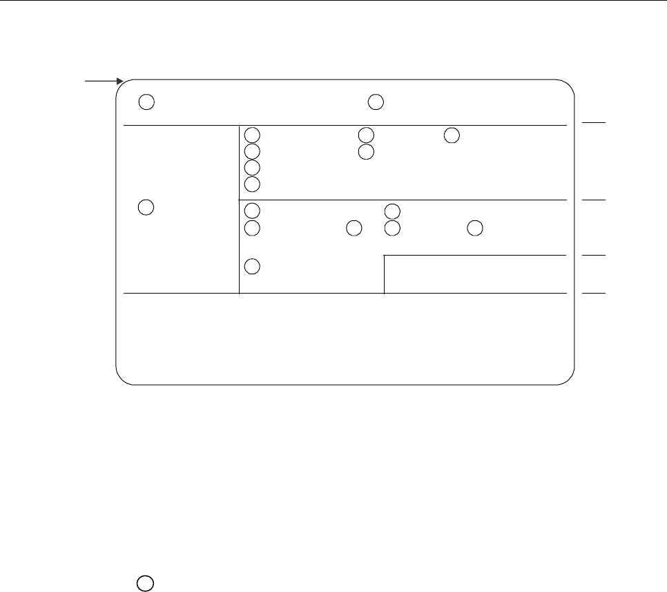
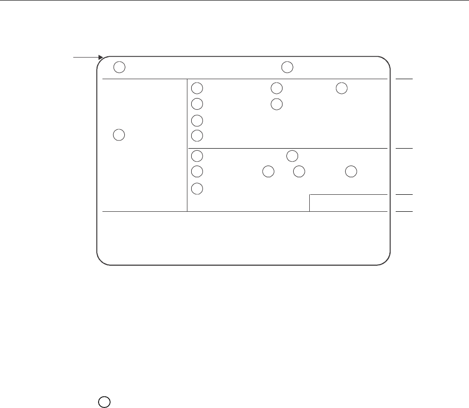
Figure 2. Location of data elements on an MRV-A
Note 1.— VIZ based on maximum printing density of 8 lines per 25.4 mm (1.0 in) and horizontal printing
density of 15 characters per 25.4 mm (1.0 in).
Note 2.— MRZ based on horizontal printing of 10 characters per 25.4 mm (1.0 in).
Note 3.— = field numbers.
Note 4.— The borderlines of the zones are not printed on the actual visa.
01 02
03 04
05
06
07
08
09
10
11
12 13 14 15
16
17
Top edge of
MRV-A
Issuing State Type of document
Zone
Zone V
I
III
II
IV
VII
*
*
*
Identification
feature
Place of issue
Number of entries
Type/Class/Category (including territorial validity)
Additional document information (Duration of stay/Conditions of
entry/Date of issue if different from “Validity from” date)
Valid from
Valid until
Document number
Name - primary identifier
Passport number
Sex
Name - secondary identifier
Date of birth
Nationality
Additional personal
information
Signature or official stamp
Upper machine readable line
Lower machine readable line
Optional control number – to be preprinted at the discretion of the issuing State either horizontally where shown in Zone I
or in Zone II or vertically anywhere along the right-hand edge of Zone V (where present).
Not to scale
16 Machine Readable Travel Documents
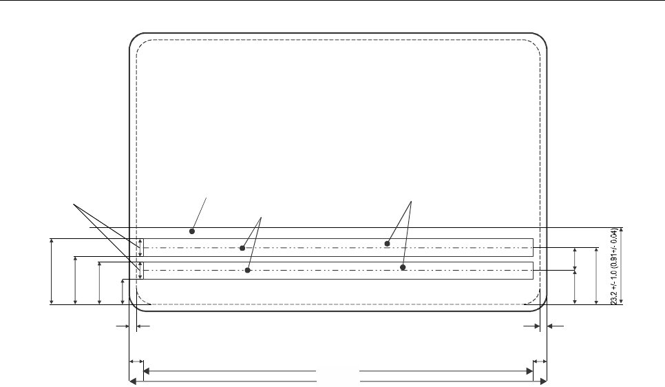
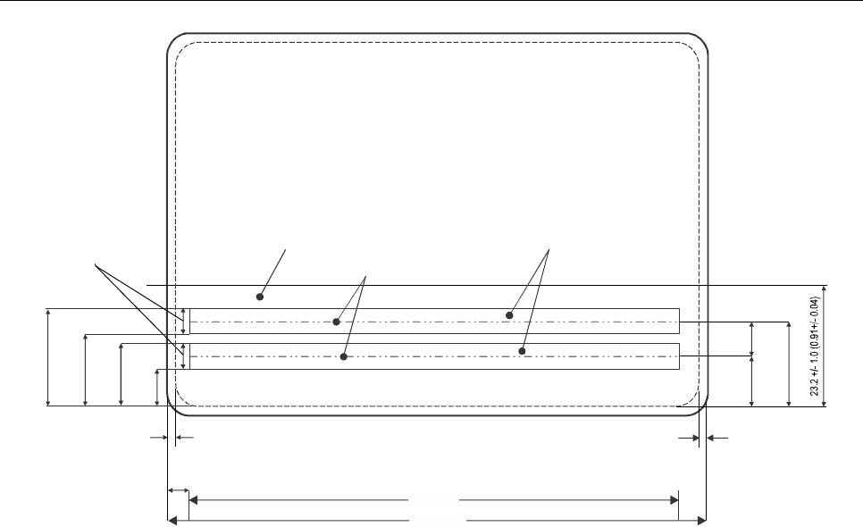
Figure 3. Schematic diagram of the Machine Readable Zone of an MRV-A
Note.— For illustration purposes, the smallest option for the 120.0 mm (4.72 in) dimension of the MRV-A
and the smallest option for the left-hand margin in the MRZ have been selected.
Machine readable zone
Reference centre line
17.9 (0.70)
13.6 (0.54)
11.55 (0.45)
7.25
(0.29)
Dimensions in millimetres
(inch dimensions in parentheses)
Printing zone
code line
Upper
Lower
4.3
(0.17)
114.0 (4.49)
119.0 (4.69)
2.0 (0.08)2.0 (0.08)
Not to scale
4.0
(0.16)
3.0
(0.12)
9.40
(0.37)
6.35
(0.25)
15.75 (0.62)
Part 7. Machine Readable Visas 17
`
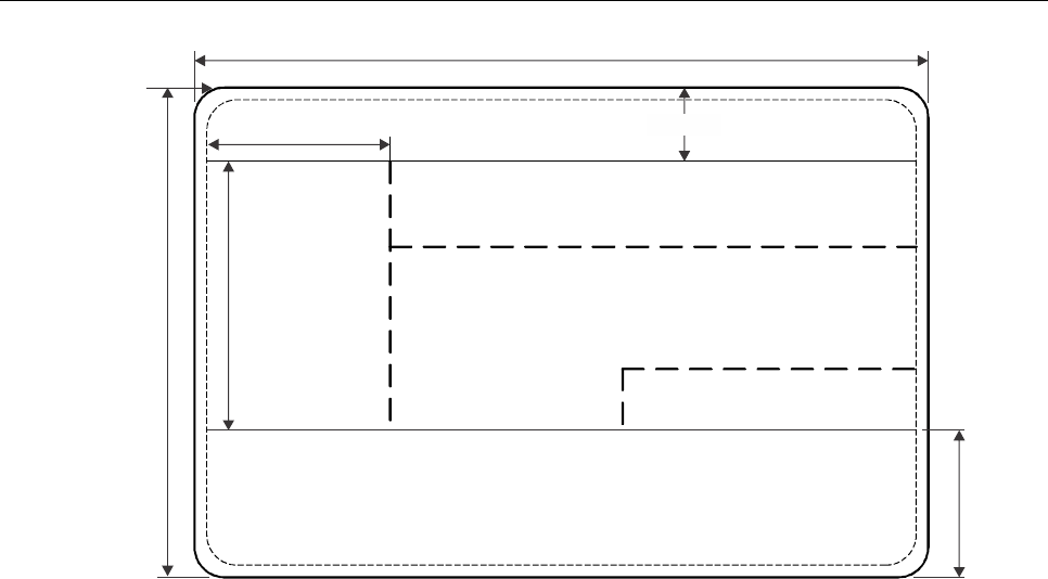
Figure 4. Nominal positioning of zones on an MRV-A
This diagram should be considered in conjunction with Section 3.3. It assumes that all the available space for data in the
VIZ is used. The line spacing in the VIZ is the closest permitted at 8 lines per 25.4 mm (1.0 in). If an issuing State
requires less information, the line spacing can be increased to print fewer lines in the VIZ.
Dotted lines indicate zone boundaries whose positions are not fixed, enabling issuing States flexibility in the presentation
of data.
The dimensions of the identification feature (normally a portrait) shall be between a minimum of 32.0 mm × 26.0 mm
(1.26 in × 1.02 in) and a maximum of 40.0 mm × 32.0 mm (1.57 in × 1.26 in). An issuing State may elect to issue an
MRV in this format without an identification feature, replacing it with a crest or symbol.
Though the portrait position is defined as a rectangular area, it may have irregular edges or, if the portrait is digitally
printed, have the background dropped out. Such techniques may be used to provide protection against fraudulent
alteration.
Affixed photographs (even if protected by a laminate) shall not be applied. Identification features shall be personalized.
120.0 +/- 1.0 (4.72 +/- 0.04)
Zone I
Zone III
Zone II
Zone IV
Zone VII
Zone V
23.2 +/- 1.0 (0.91 +/- 0.04)
Not to scale
Dimensions in millimetres
(inch dimensions in parentheses)
80.0 +/- 1.0 (3.15 +/- 0.04)
Top edge of
MRV-A
(layout 2)
29.0 +/- 3.0 (1.14 +/- 0.12)
36.0 +/- 4.0 (1.42 +/- 0.16)
Machine readable zone
12.0 (0.47)
18 Machine Readable Travel Documents
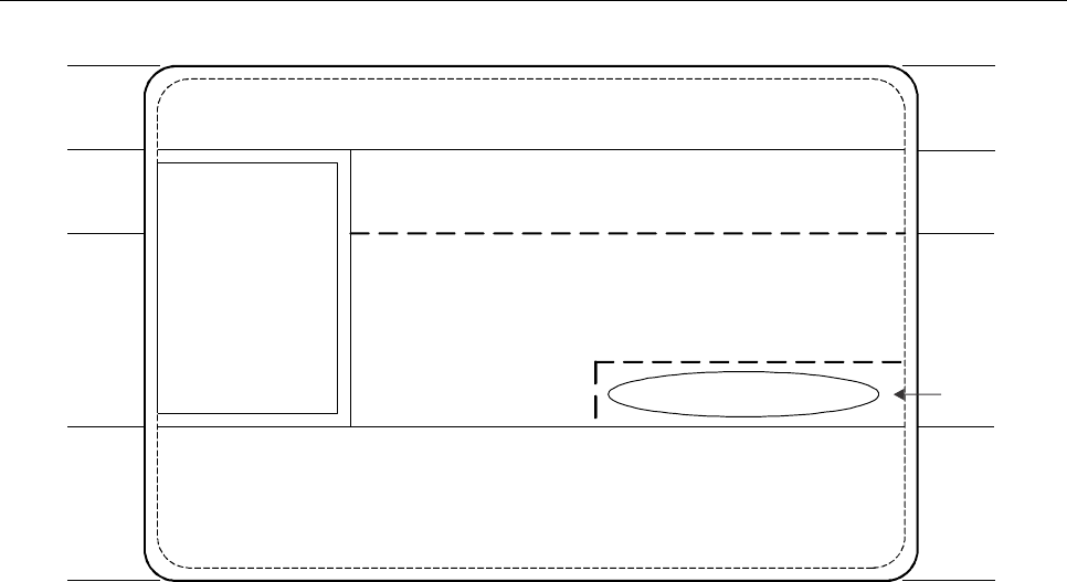
Figure 5. Data elements on an MRV-A
Note 1.— Broken lines indicate zone borders whose position may be adjusted by the issuing State to
optimize the presentation of the data. Solid lines indicate fixed zone borders. Zone border lines are not printed on the
documents.
Note 2.— Provided it is contained within the rectangular area, the identification feature may have irregular
edges.
Note 3.— An issuing State may elect to issue a visa with the identification feature replaced by a crest or
symbol.
Zone
I
III
II
IV
VII
Not to scale
Machine readable zone
Signature or official stamp
Up to
10 lines
Up to
4 lines
Identification
feature
Zone V
Issuing State
Document type
Place of issue
Number of entries
Type/Class/Category (including territorial validity)
Additional document information
Valid from Valid until
Document number
Primary identifier, Secondary identifier (Passport holder)
Passport number
Sex Date of birth
Nationality
Additional personal information
Part 7. Machine Readable Visas 19
5. TECHNICAL SPECIFICATIONS FOR FORMAT-B
MACHINE READABLE VISAS (MRV-B)
This section defines the specifications which are unique to Format-B machine readable visas (MRV-B) and are
necessary for global interoperability. Specifications are included for the discretionary expansion of the machine readable
data capacity of the MRV beyond that defined for global interchange. The MRV-B is suitable for use by States who wish
to maintain a clear area on the passport visa page adjacent to the visa, so as to allow a seal to be placed on the visa
and the passport page on which it is affixed.
5.1 Dimensions and Placement of the MRV-B
The dimensions and placement of the MRV-B shall be as follows:
MRV-B nominal dimensions. The nominal dimensions of the MRV-B are based on ISO/IEC 7810, ID-2 Type Card as
follows:
74.0 mm × 105.0 mm (2.91 in × 4.13 in)
MRV-B margins. The dimensional specifications refer to the outer limits of the MRV-B. A margin of 2.0 mm (0.08 in)
along each outer edge, with the exception of the header zone, must be left clear of data.
MRV-B edge tolerances. The edges of the MRV-B shall be within the area circumscribed by the concentric rectangles as
illustrated in Figure 6.
Inner rectangle: 73.0 mm × 104.0 mm (2.87 in × 4.09 in)
Outer rectangle: 75.0 mm × 106.0 mm (2.95 in × 4.17 in)
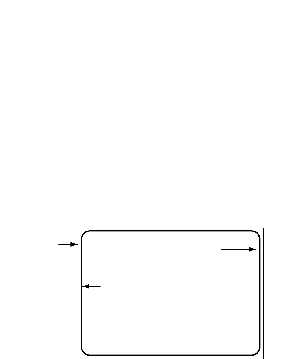
Figure 6. MRV-B dimensional illustration
Not to scale
Outer
rectangle
Inner
rectangle
Outer edge
of MRV-B

20 Machine Readable Travel Documents
MRV-B thickness. If the visa is issued as a label, the increase in thickness once the label is attached to the passport visa
page shall not exceed 0.19 mm (0.0075 in). The thickness of the area within the machine readable zone (MRZ) shall not
vary by more than 0.05 mm (0.002 in). If a protective laminate is used, it is recommended that its thickness not exceed
0.15 mm (0.006 in).
General note.— The decimal notation used in these specifications conforms to ICAO practice. This differs
from ISO practice where a decimal point (.) in imperial measurements and a comma (,) in metric measurements is used.
Placement of the MRV-B. The MRV-B shall be positioned as follows:
The MRV-B shall be located on the passport visa page such that the MRZ is coincident with and parallel to the outside
edge (reference edge) of the passport visa page, and the left edge of the MRV-B is coincident with and parallel to the left
edge of the passport visa page as defined in Appendix C, Section C.2.
The MRZ shall be located such that the two OCR lines contained therein are within the Effective Reading Zone (ERZ) as
defined in Doc 9303-3.
Only one MRV-B shall be located on a passport visa page (see Appendix C, Section C.2).
6. GENERAL LAYOUT OF THE MRV-B
The MRV-B follows a standardized layout to facilitate reading of data globally, by visual and machine readable means, to
accommodate the various requirements of States’ laws and practices and to achieve the maximum standardization
within those divergent requirements.
The standard layout incorporates space for a portrait of the holder and other identification feature(s). The inclusion of a
portrait on a visa is strongly recommended in the interests of security, but States that are not yet able to apply portraits
may fill this space with, for example, a national crest.
6.1 MRV-B Zones
An MRV-B is divided into six zones as follows:
Zone I Mandatory header
Zone II Mandatory and optional personal data elements
Zone III Mandatory and optional document data elements
Zone IV Signature (original or reproduction) or authentication
Zone V Mandatory zone for identification feature (feature optional)
Zone VII Mandatory machine readable zone (MRZ)
Note 1.— The signature in Zone IV of a visa is that of an issuing officer, not of the document holder. The
signature may be replaced or accompanied by an official stamp.
Note 2.— To facilitate inspection of visas at border control, the layout of the visa presents Zone III above
Zone II.
Note 3.— Zone VI is not available on an MRV issued in the form of a label.
Note 4.— Zones I to V constitute the Visual Inspection Zone (VIZ).

Part 7. Machine Readable Visas 21
Zones I and VII are mandatory. Certain data in Zones II and III are also mandatory. The mandatory components of these
four Zones represent the minimum data requirements for an MRV-B. The optional data elements in Zones II, III and V
and in optional Zone IV may be utilized to accommodate the diverse requirements of States, while achieving the desired
level of standardization. The data elements which may be included in the various zones and their order are set out in
Section 7.4. Section 7.4 also illustrates the dimensional specifications and tolerances for the two layouts of the MRV-B
and the technical specifications for the printing of data elements within the zones, as well as the guidelines for
positioning and adjusting the dimensional specifications of Zones I to V to accommodate the flexibility desired by issuing
States. Examples of personalized MRV-Bs are shown in Appendix A, Section A.2. Appendix B, Section B.2 illustrates
the format for the presentation of the machine readable data in Zone VII.
6.2 Content, Use and Dimensional Flexibility of Zones
The data elements to be included in the zones, the treatment of the zones and guidelines for the dimensional layout of
zones shall be as described hereunder.
Zone I identifies the issuing State and the type of document. These elements are mandatory. The order of the data
elements in this zone is left to the discretion of the issuing State.
To facilitate the checking of visas by airline personnel and control authorities, the essential details of the visa document
shall be entered in a standard sequence in Zone III while essential personal details of the holder shall be entered in a
standard sequence in Zone II. On a visa, Zone III appears above Zone II.
Zone IV provides space for an optional signature or authentication. This is normally the signature of the issuing officer or
an official stamp. The application of an official stamp elsewhere on the document is not precluded except that it must not
intrude into the MRZ or affect the legibility of entered data.
Zone VII conforms in height to the MRZ defined for all MRTDs so that the machine readable data lines fall within the
ERZ specified in Doc 9303-3, thus allowing a single reader to be used for all types and sizes of MRTDs.
All MRZ data elements are mandatory and shall be shown as defined in Section 7.2 even though an issuing State may
choose not to include a specific MRZ data element in the VIZ.
6.3 Dimensional Flexibility of Zones I to V
Zones I to V may be adjusted in size and shape within the overall dimensional specifications of the MRV-B to
accommodate the diverse requirements of issuing States. All zones, however, shall be bounded by straight lines, and all
angles where straight lines join shall be right angles (i.e. 90 degrees). It is recommended that the zone boundaries not
be printed on the MRV-B. The nominal position of the zones is shown in Section 7.4, Figure 9.
When an issuing State chooses to produce an MRV-B as a securely attached card containing a transparent or otherwise
unprintable border around the card, the available area within the zones will be reduced. The full MRV-B dimensions and
zone boundaries shall be measured from the outside edge of this border, which is the external edge of the MRV-B.
Zone I shall be adjacent and parallel to the top edge of the MRV-B and extend across the full 105.0 mm ± 1.0 mm
(4.13 in ± 0.04 in) dimension. The issuing State may vary the vertical dimension of Zone I, as required, but the
dimension shall be sufficient to allow legibility of the data elements, and the height shall not be greater than 12.0 mm
(0.47 in) as defined in Section 7.4, Figure 9.

22 Machine Readable Travel Documents
Zone V shall be located such that its left edge is coincident with the left edge of the MRV-B, as defined in Section 7.4,
Figure 9. Zone V may vary in size but any variation from the nominal dimensions shall not exceed the tolerances
specified in Section 7.4, Figure 9.
Zone V may move vertically along the left edge of the MRV-B and overlay a portion of Zone I as long as individual
details contained in either zone are not obscured. Zone V may, as a result, have its lower external boundary coincident
with the top edge of the MRZ of the MRV-B and its upper external boundary coincident with the top edge of the MRV-B.
The upper boundary of Zone III shall be coincident with the lower boundary of Zone I.
Zone III may extend to the full width of that portion of the MRV-B to the right of Zone V.
The lower boundary of Zone III (see Section 7.4, Figure 9) may be positioned at the discretion of the issuing State.
Enough space shall be left for Zone II and Zone IV (when used) below the boundary. The boundary does not need to be
straight across the 105.0 mm ± 1.0 mm (4.13 in ± 0.04 in) dimension of the MRV-B.
Normally, the upper boundary of Zone II should be coincident with the lower boundary of Zone III. The boundary does
not have to be straight across the 105.0 mm ± 1.0 mm (4.13 in ± 0.04 in) dimension of the visa. Zone II may also overlay
a portion of Zone V for the MRV-B if required. When this occurs, issuing States shall ensure that data contained in either
zone are not obscured. See Appendix A, A.2.
Zone IV, when included on the MRV-B, shall be entered on the right hand side of the visa immediately above but not
intruding into the MRZ. See Section 7.4, Figure 9.
7. DETAILED LAYOUT OF THE MRV-B
7.1 Visual Inspection Zone (VIZ) (Zones I-V)
All data in the VIZ shall be clearly legible.
Print spacing. The design of the MRV-B in Zones II and III is based on a vertical line spacing of a maximum of 8 lines
per 25.4 mm (1.0 in) and a horizontal printing density of a maximum of 15 characters per 25.4 mm (1.0 in). This spacing
has been chosen as the smallest in which information is clear and legible. If any optional field or data element is not
used, the entered data may be spread out in the VIZ of the MRV-B consistent with the requirement for sequencing zones
and data elements. This horizontal printing density and the font and the vertical line spacing may be adjusted at the
discretion of each State, provided that in the VIZ all data shall be printed in a size such that they can be easily read and
assimilated by a person with normal eyesight. Typical configurations are shown in Appendix A, A.2. Zone VII, the
mandatory MRZ, shall be printed with a line spacing as defined in Section 7.4, Figure 8, and a horizontal printing density
of 10 characters per 25.4 mm (1.0 in).

Part 7. Machine Readable Visas 23
7.1.1 Data element directory
7.1.1.1 Visual inspection zone — Data element directory
Field/
zone no.
Data element
Specifications
Maximum no.
of character
positions
References
and notes*
01/I
Mandatory
Issuing State
The State responsible for issuing the
MRV-B. This shall be personalized, the
type font being selected at the discretion
of the issuing State. For transliteration
rules, refer to Doc 9303-3.
Variable
Notes a, c, d,
e, i.
02/I
Mandatory
Document
The word or words in the language of the
issuing State for the document (visa or
other appropriate document) which
confers on the holder that State’s authority
to travel to a port of entry in its territory.
Variable
Notes a, c, d,
e, i.
03/III
Mandatory
Place of issue
Post/location (usually a city) where the
MRV-B is issued. A translation of the
name into one or more languages, one of
which should be English, French or
Spanish, shall be given when the
translated name is more familiar to the
international community.
15
Notes a, b, c, i,
k.
04/III
Mandatory
Valid from (date)
In most cases this will be the date of issue
of the MRV-B and indicates the first date
from which the MRV-B can be used to
seek entry. For some States the date of
issue and the date the visa becomes valid
may differ. In such cases the latter shall
be indicated in this field and the date of
issue may be shown in Field 09 (see
below). Date formats are specified in
9303-3.
8
Notes a, b, c, i,
k.
05/III
Mandatory
Valid until (date)
In most cases this will be the date of
expiry of the MRV-B and indicates the last
day on which the visa can be used to seek
entry. For some States this will be the
date by or on which the holder should
have left the country concerned. Date
formats are specified in 9303-3.
8
Notes a, b, c, i,
k.
06/III
Mandatory
Number of
entries
The number of entries for which the visa is
valid.
8
Notes a, b, c, i,
k.
24 Machine Readable Travel Documents
Field/
zone no.
Data element
Specifications
Maximum no.
of character
positions
References
and notes*
07/III
Mandatory
Document
number
The number given to the visa by the
issuing State.
13
Notes a, b, c, i,
j, k.
08/III
Mandatory
Type/class/
category
This field shall include one or more of the
following elements:
• the issuing State’s indication of the
type and/or class of visa granted in
accordance with the law/practice of
that State;
• the broad categorization of the type of
visa granted, e.g. visitor/resident/
temporary resident/student/diplomat,
etc., in accordance with the
law/practice of the issuing State;
• any limitations on the territorial validity
of the visa.
46
Notes a, b, c, i,
k.
09/III
Optional
Additional
information
This field may include necessary
endorsements as to entitlements which
attach to the visa. The issuing State may
also use this field to include a) the
maximum authorized duration of stay;
b) conditions related to the granting of the
visa; c) date of issue if different from
“Valid from” date; and d) record of any
fees paid.
Note g.
10,11/II
Mandatory
Name
See Doc 9303-3.
Variable
Notes a, c, i, k.
10/II
Mandatory
Primary identifier
See Doc 9303-3.
Variable
Notes a, c, i, k.
11/II
Optional
Secondary
identifier
See Doc 9303-3.
Variable
Notes a, c, i.
12/II
Optional
Passport number
The number of the passport or other travel
document in which the MRV-B is placed.
Variable
Notes a, b, c,
g, i, j.

Part 7. Machine Readable Visas 25
Field/
zone no.
Data element
Specifications
Maximum no.
of character
positions
References
and notes*
13/II
Optional
Sex
Sex of MRV-B holder, when included, is to
be specified by use of the single initial
commonly used in the language of the
State of issue. If translation into English,
French or Spanish is necessary, followed
by an oblique and the capital letter F for
female, M for male, or X for unspecified.
3
Fixed
Notes a, f, g.
14/II
Optional
Date of birth
See Doc 9303-3.
9
Notes a, b, c,
k.
15/II
Optional
Nationality
See Doc 9303-3.
Variable
Notes a, h, k.
16/IV
Optional
Signature or
other
authorization
An authorization which may be the
signature of an issuing official or an official
stamp.
17/V
Mandatory
Identification
feature
This field shall appear on the document
and should contain a portrait of the holder.
If included, the portrait shall have a
nominal size of 35.5 ± 3.5 mm
(1.40 ± 0.14 in) × 28.5 ± 2.5 mm
(1.12 ± 0.1 in).
If a State does not place an identification
feature in this field, a national symbol or
logo may be inserted instead.
See Doc 9303-3, Section 3.9 for additional
specifications for the portrait.
Note e.
* Notes can be found in the last portion of sub-section 7.2.2.2.
7.2 Machine Readable Zone (MRZ) (Mandatory Zone VII)
7.2.1 MRZ position, data elements, print specifications and print position in the MRZ
7.2.1.1 MRZ position
The MRZ is located at the bottom of the MRV-B. Section 7.4, Figure 8, shows the nominal position of the data in the
MRZ.

26 Machine Readable Travel Documents
7.2.1.2 Data elements
The data elements corresponding to Fields 01, 05, 10, 11, and 13 to 15 of the VIZ are mandatory in the MRZ and shall
be printed in machine readable form in the MRZ, beginning with the leftmost character position in each field in the
sequence indicated in the data structure specifications shown below. Appendix B, Section B.2, indicates the structure of
the MRZ.
7.2.1.3 Print specifications
Machine readable data shall be printed in OCR-B type font, size 1, constant stroke width, as specified in Doc 9303-3.
The MRZ shall be printed with the line spacing as defined in Section 7.4, Figure 8, and a horizontal printing density of 10
characters per 25.4 mm (1.0 in).
7.2.1.4 Print position
The position of the left-hand edge of the first character shall be 4.0 mm ± 1.0 mm (0.16 in ± 0.04 in) from the left-hand
edge of the document. Reference centre lines for the two OCR lines and a nominal starting position for the first character
of each line are shown in Section 7.4, Figure 8. The positioning of the characters is indicated by those reference lines
and by the printing zones of the two code lines in Section 7.4, Figure 8 .
7.2.2 Data Structure of Machine Readable Data for the MRV-B
7.2.2.1 Data structure of the upper machine readable line
MRZ field
character
positions
(line 1)
Field no.
in VIZ
Data element
Specifications
Number of
characters
References
and notes*
1 to 2
Type of
document
Capital letter V to designate an
MRV. One additional character may
be used, at the discretion of the
issuing State, to designate a
particular type of visa. If the second
character position is not used for
this purpose, it shall be filled by the
filler character (<).
2
Notes a, b, c,
e.
3 to 5
1
Issuing State
See Doc 9303-3.
3
Notes a, c, e.
6 to 36
10, 11
Name
See Doc 9303-3.
31
Notes a, c, e.
Punctuation
in the name
Representation of punctuation is not
permitted in the MRZ.
Doc 9303-3.

Part 7. Machine Readable Visas 27
MRZ field
character
positions
(line 1)
Field no.
in VIZ
Data element
Specifications
Number of
characters
References
and notes*
Apostrophes
in the name
Components of the name in the VIZ,
separated by apostrophes shall be
combined, and no filler character (<)
shall be inserted.
Example:
VIZ: D’ARTAGNAN
MRZ: DARTAGNAN
Doc 9303-3.
Hyphens
in the name
Hyphens (-) in the name shall be
converted to the filler character (<)
(i.e. hyphenated names shall be
represented as separate
components).
Example:
VIZ: MARIE-ELISE
MRZ: MARIE<ELISE
Doc 9303-3.
Commas
When a comma is used in the VIZ to
separate the primary and secondary
identifiers, the comma shall be
omitted in the MRZ and the primary
and secondary identifiers shall be
separated by two filler characters
(<<).
When a comma is used in the VIZ to
separate two name components, it
shall be represented in the MRZ by
a single filler character (<).
Doc 9303-3.
Name suffixes
Name suffixes (e.g. Jr., Sr., II or III)
shall not be included in the MRZ
except as permitted by Doc 9303-3
as components of the secondary
identifier.
Doc 9303-3.
Filler
When all components of the primary
and secondary identifiers and
required separators (filler
characters) do not exceed 31
characters in total, all name
components shall be included in the
MRZ and all unused character
positions shall be completed with
filler characters (<) repeated up to
position 36 as required.

28 Machine Readable Travel Documents
MRZ field
character
positions
(line 1)
Field no.
in VIZ
Data element
Specifications
Number of
characters
References
and notes*
Truncation of
the name
When the primary and secondary
identifiers and required separators
(filler characters) exceed the
number of character positions
available for names (i.e. 31), they
shall be truncated as follows:
Doc 9303-3,
Notes a, c, e.
Characters shall be removed from
one or more components of the
primary identifier until three
character positions are freed, and
two filler characters (<<) and the first
character of the first component of
the secondary identifier can be
inserted. The last character (position
36) shall be an alphabetic character
(A through Z). This indicates that
truncation may have occurred.
Further truncation of the primary
identifier may be carried out to allow
characters of the secondary
identifier to be included, provided
that the name field shall end with an
alphabetic character (position 36).
This indicates that truncation may
have occurred.
When the name consists of only a
primary identifier which exceeds the
number of character positions
available for the name, i.e. 31,
characters shall be removed from
one or more components of the
name until the last character in the
name field is an alphabetic
character.
* Notes can be found in the last portion of sub-section 7.2.2.2.

Part 7. Machine Readable Visas 29
7.2.2.2 Data structure of the lower machine readable line
MRZ field
character
positions
(line 2)
Field no.
in VIZ
Data element
Specifications
Number of
characters
References
and notes*
1 to 9
07 or
12
Passport or
document
number
At the discretion of the issuing State,
either the passport number or the
visa number shall be used in this
field; however, the latter option can
only be exercised where the visa
number has 9 characters or fewer.
Any special characters or spaces in
the number shall be replaced by the
filler character (<). The number shall
be followed by the filler character (<)
repeated up to position 9 as required.
9
Notes a, b, c,
e, j.
10
Check digit
See Doc 9303-3.
1
Notes b, e.
11 to 13
15
Nationality
See Doc 9303-3.
3
Notes a, c, e,
h.
14 to 19
14
Date of birth
See Doc 9303-3.
6
Notes b, c, e.
20
Check digit
See Doc 9303-3.
1
Note b.
21
13
Sex
F = Female; M = Male;
< = non-specified.
1
Notes a, c, f,
g.
22 to 27
5
Valid until
(date)
In most cases this will be the date of
expiry of the MRV-B and indicates
the last day on which the visa can be
used to seek entry. For some States
this will be the date by or on which
the holder should have left. Date
formats are specified in 9303-3.
6
Notes b, e.
28
Check digit
See Doc 9303-3.
1
Note b.
29 to 36
Optional data
elements
For optional use of the issuing State.
Unused character positions shall be
completed with the filler character (<)
repeated up to position 36 as
required.
8
Notes a, b, c,
e.

30 Machine Readable Travel Documents
* Notes:
a) Alphabetic characters (A–Z). National characters may be used in the VIZ. In the MRZ, only those characters
specified in Doc 9303-3 shall be used.
b) Numeric characters (0–9). National numerals may be used in the VIZ. In the MRZ, only those characters
specified in Doc 9303-3 shall be used.
c) Punctuation or other special characters may be used in the VIZ. In the MRZ, only the filler character specified in
Doc 9303-3 shall be used.
d) The lengths of fields 01 and 02 are undefined, depending on type font and limits set by MRV-B size and
position of other fields.
e) The field caption is not printed on the document.
f) Where an issuing State or organization does not want to identify the sex, the filler character (<) shall be used in
this field in the MRZ and an X in this field in the VIZ.
g) The use of a caption to identify a field is at the option of the issuing State.
h) United Nations Laissez-passer are issued to officials of the United Nations Organization under the terms of the
Convention on the Privileges and Immunities of the United Nations of 13 February 1946 and to officials of the
Specialized Agencies of the United Nations under the terms of the Convention on the Privileges and Immunities
of the Specialized Agencies of the United Nations of 21 November 1947. In the case of visas entered in the
United Nations Laissez-passer, in keeping with the international character of United Nations officials, nationality
shall not be shown. Instead the appropriate code shall be entered in accordance Doc 9303-3.
i) The number of characters (in the field length) includes any blank spaces.
j) The number of characters in the VIZ may be variable; however, if the document number has more than 9
characters, the 9 principal characters shall be shown in the MRZ in character positions 1 to 9.
k) The field caption shall be printed on the document.
7.2.3 Examples of Names of the Holder in the MRZ
Note.— In the following examples, the document is assumed to be a visa issued by the State of Utopia.
The first five characters of the upper machine readable line are coded “V<UTO”.
a) Usual representation:
Name: Anna Maria Eriksson
VIZ: ERIKSSON, ANNA MARIA
MRZ (upper line): V<UTOERIKSSON<<ANNA<MARIA<<<<<<<<<<<
b) Central primary identifier:
Name: Deborah Heng Ming Lo
VIZ: HENG, DEBORAH MING LO
MRZ (upper line): V<UTOHENG<<DEBORAH<MING<LO<<<<<<<<<<

Part 7. Machine Readable Visas 31
c) Hyphen as part of the name:
Name: Susie Margaret Smith-Jones
VIZ: SMITH-JONES, SUSIE MARGARET
MRZ (upper line): V<UTOSMITH<JONES<<SUSIE<MARGARET<<<<
d) Apostrophe as part of the name:
Name: Enya Siobhan O’Connor
VIZ: O’CONNOR, ENYA SIOBHAN
MRZ (upper line): V<UTOOCONNOR<<ENYA<SIOBHAN<<<<<<<<<<
e) Multiple name components:
Name: Martin Van Der Muellen
VIZ: VAN DER MUELLEN, MARTIN
MRZ (upper line): V<UTOVAN<DER<MUELLEN<<MARTIN<<<<<<<<
f) No secondary identifier:
Name: Arkfreith
VIZ: ARKFREITH
MRZ (upper line): V<UTOARKFREITH<<<<<<<<<<<<<<<<<<<<<<
7.2.3.1 Truncated names — Secondary identifier truncated
a) One or more name components truncated to initials:
Name: Nilavadhanananda Chayapa Dejthamrong Krasuang
VIZ: NILAVADHANANANDA, CHAYAPA DEJTHAMRONG KRASUANG
MRZ (upper line): V<UTONILAVADHANANANDA<<CHAYAPA<DEJ<K
b) One or more name components truncated:
Name: Nilavadhanananda Arnpol Petch Charonguang
VIZ: NILAVADHANANANDA, ARNPOL PETCH CHARONGUANG
MRZ (upper line): V<UTONILAVADHANANANDA<<ARNP<PE<CHARO
7.2.3.2 Truncated names — Primary identifier truncated
a) One or more components truncated to initials:
Name: Dingo Potoroo Bennelong Wooloomooloo Warrandyte Warnambool
VIZ: BENNELONG WOOLOOMOOLOO WARRANDYTE WARNAMBOOL, DINGO POTOROO
MRZ (upper line): V<UTOBENNELONG<WOOLOOMOOLOO<WAR<W<<D

32 Machine Readable Travel Documents
b) One or more components truncated:
Name: Dingo Potoroo Bennelong Wooloomooloo Warrandyte Warnambool
VIZ: BENNELONG WOOLOOMOOLOO WARRANDYTE WARNAMBOOL, DINGO POTOROO
MRZ (upper line): V<UTOBENNELONG<WOOLOOM<WAR<WA<<DINGO
c) One or more components truncated to a fixed number of characters:
Name: Dingo Potoroo Bennelong Wooloomooloo Warrandyte Warnambool
VIZ: BENNELONG WOOLOOMOOLOO WARRANDYTE WARNAMBOOL, DINGO POTOROO
MRZ (upper line): V<UTOBENN<WOOL<WARR<WARN<<DINGO<POTO
7.2.3.3 Names that just fit, indicating possible truncation by letter in the last position of the name field, but which are
not truncated
Name: Stephen Trevor Papandropoulous
VIZ: PAPANDROPOULOUS, STEPHEN TREVOR
MRZ (upper line): V<UTOPAPANDROPOULOUS<<STEPHEN<TREVOR
Note.— Even though there is an alphabetic character in the 36th character position of this MRV-B upper
machine readable line, this name has not been truncated but it shall be assumed that it has been truncated.
7.3 Portrait
Portrait. For the MRV Format-B the rectangular area defined in the data element directory as Zone V should contain a
portrait. Such portrait, if included, shall represent only the holder of the MRV-B.
Portrait edges. The portrait may have irregular edges. When a digitally printed reproduction is used, the background of
the portrait may be dropped out in order to provide protection against forgery or substitution.
Zone V without an identification feature. A standard default image, such as a national symbol, crest or wording, should
be selected and used in Zone V when an identification feature is not included.
Part 7. Machine Readable Visas 33
7.4 MRV-B Diagrams
Figure 7. Location of data elements on an MRV-B.
Note 1.— VIZ based on maximum printing density of 8 lines per 25.4 mm (1.0 in) and horizontal printing
density of 15 characters per 25.4 mm (1.0 in).
Note 2.— MRZ based on horizontal printing of 10 characters per 25.4 mm (1.0 in).
Note 3.— = field numbers.
Note 4.— The borderlines of the zones are not printed on the actual visa.
Zone
I
III
II
IV
VII
Issuing State
01 02
03
06
08
09
10
12 13 14 15
16
11
04
07
05
17
Top edge of
MRV-B
Identification
feature
Zone V
Type of document
Place of issue Valid from
*
*
*
Valid until
Number of entries Document number
Type/Class/Category (including territorial validity)
Additional document information (Duration of stay/Conditions
of entry/Date of issue if different from”Validity from” date)
Name - primary identifier Name - secondary identifier
Passport number
Sex Date of birth
Nationality
Additional personal information
Signature or official stamp
Upper machine readable line
Lower machine readable line
Not to scale
Optional control number – to be preprinted at the discretion of the issuing Sate either horizontally where shown
in Zone I or in Zone II or vertically anywhere along the right-hand edge of Zone V (where present).
34 Machine Readable Travel Documents
Figure 8. Schematic diagram of the Machine Readable Zone of an MRV-B.
Note.— For illustration purposes, the smallest option for the 105.0 mm (4.13 in) dimension of the MRV-B
and the smallest option for the left-hand margin in the MRZ have been selected.
93.3 (3.67)
104.0 (4.09)
2.0 (0.08)
Not to scale
9.40
(0.37)
6.35
(0.25)
15.75
(0.62)
Dimensions in millimetres
(inch dimensions in parentheses)
2.0 (0.08)
3.0
(0.12)
17.9 (0.70)
13.6 (0.54)
11.55
(0.45)
7.25
(0.29)
Printing zone
code line
Upper
Lower
Machine readable zone
Reference centre line
4.3
(0.17)
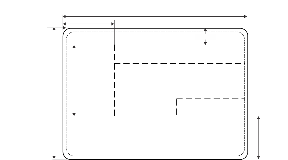
Part 7. Machine Readable Visas 35
Figure 9. Nominal positioning of zones on an MRV-B.
This diagram should be considered in conjunction with Section 6.3. It assumes that all the available space for data in the
Visual Inspection Zone is used. The line spacing in the VIZ is the closest permitted at 8 lines per 25.4 mm (1.0 in). If an
issuing State requires less information the line spacing can be increased to print fewer lines in the VIZ.
Dotted lines indicate zone boundaries whose positions are not fixed, enabling issuing States flexibility in the presentation
of data.
The dimensions of the identification feature (normally a portrait) shall be between a minimum of 32.0 mm × 26.0 mm
(1.26 in × 1.02 in) and a maximum of 39.0 mm × 31.0 mm (1.54 in × 1.22 in). An issuing State may elect to issue an
MRV in this format without an identification feature, replacing it with a crest or symbol.
Though the portrait position is defined as a rectangular area, it may have irregular edges or, if the portrait is digitally
printed, have the background dropped out. Such technique may be used to provide protection against fraudulent
alteration.
Affixed photographs (even if protected by a laminate) shall not be applied. Identification features shall be personalized.
Zone V
Dimensions in millimetres
(inch dimensions in parentheses)
74.0 +/- 1.0 (2.91 +/- 0.04)
Top edge of
MRV-B
(layout 2)
35.5 +/- 3.5 (1.40 +/- 0.14)
Machine readable zone
28.5 +/- 2.5 (1.12 +/- 0.10)
12.0 (0.47)
105.0 +/- 1.0 (4.13 +/- 0.04)
Not to scale
Zone VII
Zone IV
Zone II
Zone I
Zone III
23.2 +/- 1.0 (0.91 +/- 0.04)
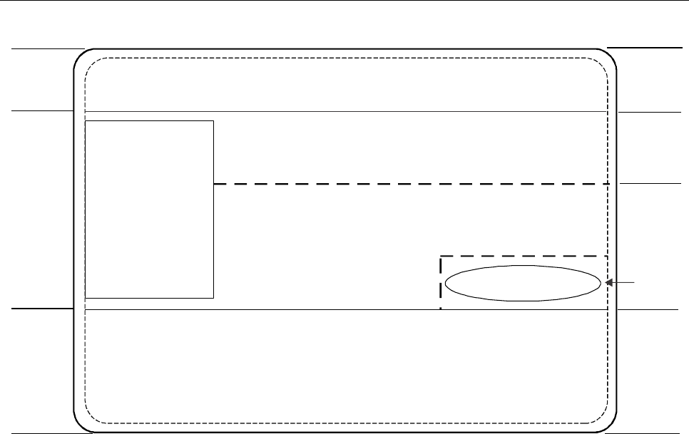
36 Machine Readable Travel Documents
Figure 10. Data elements on an MRV-B.
Note 1.— Broken lines indicate zone borders whose position may be adjusted by the issuing State to
optimize the presentation of the data. Solid lines indicate fixed zone borders. Zone border lines are not printed on the
document.
Note 2.— Provided it is contained within the rectangular area, the identification feature may have irregular
edges.
Note 3.— An issuing State may elect to issue a visa with the identification feature replaced by a crest or
symbol.
Zone
I
III
II
IV
VII
Not to scale
Machine readable zone
Signature or official stamp
Identification
feature
Zone V
Issuing State
Document type
Place of issue
Number of entries
Type/Class/Category (including territorial validity)
Additional document information
Valid from Valid until
Document number
Primary identifier, Secondary identifier (Passport holder)
Passport number
Sex Date of birth
Nationality
Additional personal information
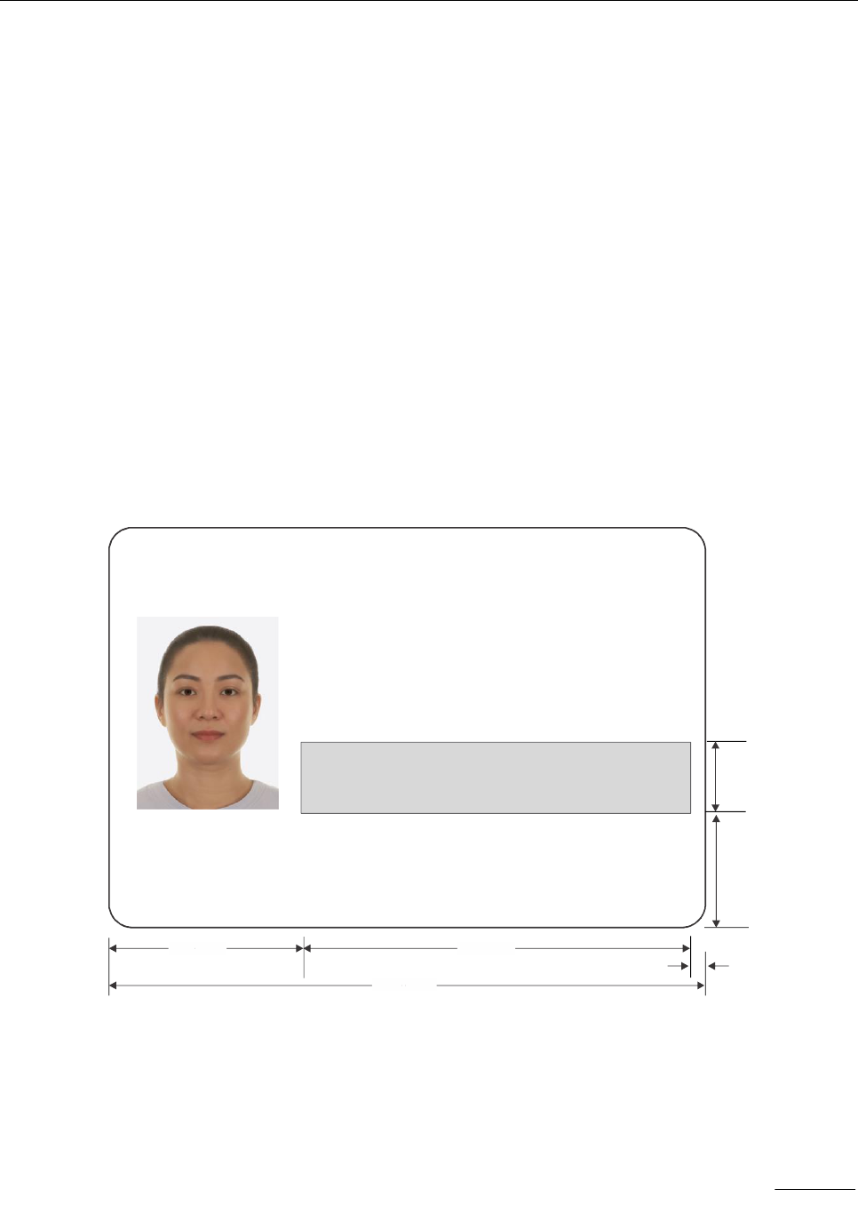
Part 7. Machine Readable Visas 37
8. USE OF OPTIONAL BARCODES ON
MACHINE READABLE VISAS
8.1 Scope
This section defines the specifications governing the use of one or more bar codes on an MRV, at the discretion of the
issuing State, to allow expansion of the machine readable data capacity.
8.2 Definition
A bar code is defined as a linear or two-dimensional bar code conforming with the specifications defined herein and
capable of representing data therein and encoded data read therefrom.
8.3 Location of Bar Code(s)
Figures 11 and 12 illustrate the location of a bar code on the MRV-A and MRV-B, respectively, as well as the specifications
for the exact placement and overall dimensions of the area to house any optional bar codes. It should be noted that the
height and width of the bar code(s) area can vary up to the maximum dimensions shown. In defining these dimensions,
the trade-off between optional expanded machine readable data capacity desired and accommodation of mandatory and
optional details (VIZ) should be considered.
Figure 11. MRV-A with optional linear
or two dimensional bar code
20/3/24
No. 1
Optional Linear or 2D barcode data
Note: This area includes any quiet areas required by the selected
symbology
UTOPIA VISA
Place of Issue/Lieu de délivrance
Valid from/Valide partir duà Valid until/Valide jusqu’au
ZENITH
10 DEC 91 /DÉC 10 DEC 96 /DÉC
No. of Entries/ Nombre d’entrées
MULTIPLE
Document No./N° de document
M123889546
Type/Type
BUSINESS MULTIPLE
Surname, Given names/ Nom, Prénoms
ERIKSSON ANNA MARIA
Passport Number/N° de passeport Sex
Date of Birth/
Date de naissance
Nationality/
Nationalité
XXX12 AUG/AOÛT 74F/F
L8988901C
V<UTOERIKSSON<<ANNA<MARIA<<<<<<<<<<<<<<<<<<<
L8988901C4XXX F96121096ZE184226B<<<<<<7408122
18.35
(0.72)
23.20 +/- 1.0
(0.91 +/- 0.04)
/Sexe
3.0 (0.12)
78.0 3.07) (
120.0 (4.72)
39.0 (1.54)
Dimensions in millimetr se
(inch dimensions in parentheses)
Not to scale
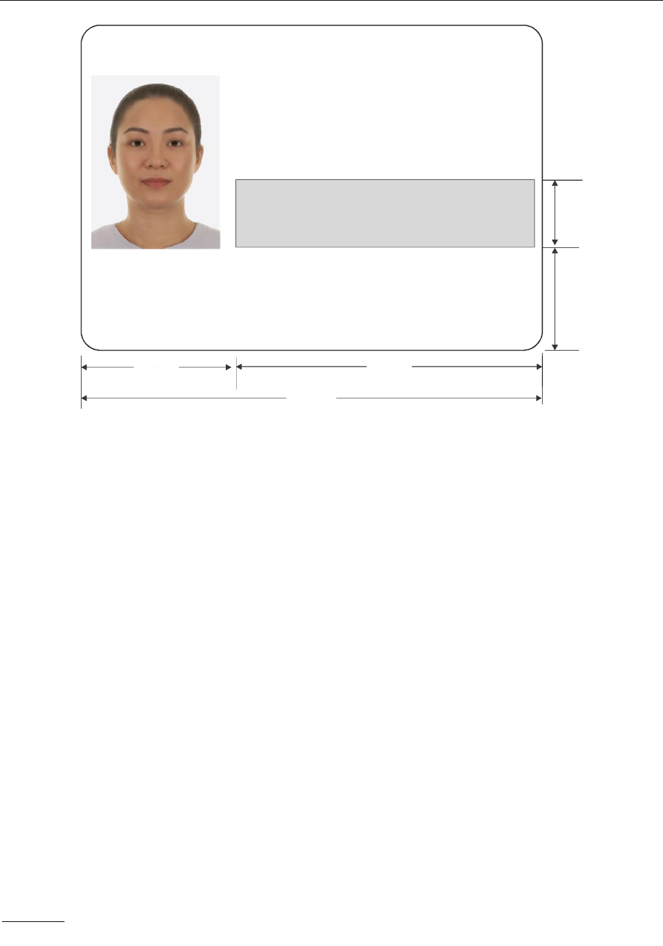
38 Machine Readable Travel Documents
Figure 12. MRV-B with optional linear
or two dimensional bar code
8.4 Quality of Bar Code(s)
The bar code(s) included in the bar code(s) area shall meet the overall symbol grade defined for the chosen symbology
(symbologies) that allows symbols to be read, following final assembly of the MRV, most times in a single pass.
8.5 Symbologies and Logical Data Structure
In order to have the capability to support global data interchange with authorized bodies such as airlines, the bar code
symbology selected must offer sufficient data storage capacity to accommodate all mandatory data elements included in
the mandatory data groups and in any optional data groups which may be selected from the logical data structure as
developed for optional capacity expansion technologies. Furthermore, the associated reading software must be available
in the public domain.
8.6 Machine Reading of the Bar Code(s)
To enable accurate reading of bar code(s) coexisting with security treatments (e.g. background security printing) in the
bar code(s) area, and the use of a single machine reader for reading the MRZ and the bar code(s), where desired by a
State, the bar code(s) optionally included on the MRV shall be printed such that the bar code(s) absorb(s) in the B900
band as defined in ISO 1831 (i.e. near infra-red). The bar code(s) may be visually legible.
20/3/24
No. 1
Optional Linear or 2D barcode data
Note: This area includes any quiet areas required by the
selected symbology
UTOPIA
VISA
Place of Issue/Lieu de délivrance
Valid from/Valide partir duà Valid until/Valide jusqu’au
ZENITH
10 DEC 91 /DÉC 10 DEC 96 /DÉC
No. of Entries/ Nombre d’entrées
MULTIPLE
Document No./N° de document
M123889546
Type/Type
BUSINESS MULTIPLE
Surname, Given names/ Nom, Prénoms
ERIKSSON ANNA MARIA
Passport Number/N° de passeport
Sex/Sexe
Date of Birth/
Date de naissance
Nationality/
Nationalité
XXX12 AUG/AOÛT 74
F/F
L8988901C
V<UTOERIKSSON<<ANNA<MARIA<<<<<<<<<<<
L8988901C4XXX F9612109<<<<<<<<7408122
18.35
(0.72)
23.20 +/- 1.0
(0.91 +/- 0.04)
70.0 2.76) (
105.0 (4.13)
35.0 (1.38)
Dimensions in millimetr se
(inch dimensions in parentheses)
Not to scale

Part 7. Machine Readable Visas 39
In determining the placement of the bar code on the MRV, issuing States shall accommodate any special needs or
operating conditions of the symbology (symbologies) such as bit area and error correction level. In addition, sufficient
marginal space shall be included to accommodate “quiet areas”.
Issuing States are encouraged to locate the bar code(s) area nearest to the top edge of the MRZ to allow for possible
use of the optical sensing components from the OCR reader, supported by bar code interpretation logic, to
accommodate reading of optional bar code data.
The bar code(s) optionally included in the bar code(s) area of the MRV shall not interfere with the accurate reading of
data from the MRZ.
9. USE OF OPTIONAL DIGITAL SEALS FOR VISA DOCUMENTS
Doc 9303-13 specifies visible digital seals (VDS) for non-electronic documents. In this section the specific rules and
requirements for the use of visible digital seals on Visa documents are described.
9.1 Content and Encoding Rules
9.1.1 Header
The Document Feature Definition Reference for this use case is 93dec. The Document Type Category for visas is
0 x 01. Otherwise, the content of the header is the same as defined in Doc 9303-13, Section 3.1.1.
9.1.2 Document Features of a VDS for Visas
The following document features are stored in the seal:
Machine Readable Zone (REQUIRED)
The Machine Readable Zone (MRZ) of a visa contains the following information:
• issuing state
• primary and secondary identifiers
• passport or visa number
• nationality of the document holder
• date of birth of the document holder
• sex of the document holder
• validity period (valid until…)
Some States may not issue paper-based visas, but instead use a domestic database to store visa applications, and
merely attach a confirmation sticker to the passport. If such States choose to adopt this standard for such stickers, the
above information SHALL be encoded as either the MRZ of an MRV-A or MRV-B.

40 Machine Readable Travel Documents
Additionally, the following document features are stored:
Number of Entries (OPTIONAL)
The number of times the visa holder may enter the territory for which the visa is valid.
Duration of Stay (REQUIRED)
This feature denotes the number of days, months or years during which the visa holder may stay in the territory for which
the visa is valid. Note that this is distinct from the “valid until” date of the MRZ, which is already stored in the visa MRZ.
First, in most cases, this “valid until” field of the visa MRZ will be the date of expiry of the MRV and indicates the last day
on which the visa can be used to seek entry. For some States, this will be the date by or on which the holder should
have left. Second, for some issuing States, the stay must be continuous, and for others, the stay can spread over
several periods. Thus, to avoid ambiguity during validation, the feature for the duration of stay is required.
Passport Number (REQUIRED)
This feature denotes the number of the passport to which the visa sticker is attached. The passport number might
already be present in the MRZ. At the discretion of the issuing State, either the passport number or the visa number
SHALL be used in the document number field of the visa MRZ; however, the latter option can only be exercised where
the visa number has nine characters or fewer. To avoid ambiguity during validation, the field for the passport number
(separate from the MRZ) is required.
Visa Type (OPTIONAL)
This feature encodes the type of the visa. The field is especially intended to be used, if the type of the visa is not
encoded as the second letter of the MRZ.
Additional Feature Field (OPTIONAL)
Reserved for future use. This field is OPTIONAL, and intended to store additional verification information in future
versions of this standard.
9.1.3 Encoding Rules for Document Features
In the following, the digital encoding of document features of the visa seal is defined.
MRZ of MRV-A (see Section 4.2.2)
Tag: 0 x 01
Min. Length: 48 Byte
Max. Length: 48 Byte Value Type: Alphanumeric
Required: Required (if visa is of type MRV-A)
Content: The first line of the MRZ of an MRV-A (44 characters) and the first 28 characters of the second line of the
MRZ of an MVR-A, concatenated and encoded by C40. The filler symbol < in the MRZ is replaced by <SPACE> prior to
encoding by C40.
MRZ of MRV-B (see Section 7.2.2)
Tag: 0 x 02
Min. Length: 44 Byte
Max. Length: 44 Byte Value Type: Alphanumeric
Required: Required (if visa is of type MRV-B)
Content: The first line of the MRZ of an MRV-B (36 characters) and the first 28 characters of the
second line of the MRZ of an MVR-B, concatenated and encoded by C40. The filler symbol < in the MRZ is replaced by
<SPACE> prior to encoding by C40.

Part 7. Machine Readable Visas 41
Number of Entries
Tag: 0 x 03
Min. Length: 1 Byte
Max. Length: 1 Byte Value Type: Integer
Required: Optional
Content: The integer in the range of 0-255dec encodes the number of allowed entries. A value of 0 denotes
unlimited entries.
Duration of Stay
Tag: 0 x 04
Min. Length: 3 Byte
Max. Length: 3 Byte Value Type: Integer
Required: Mandatory
Content: The duration of stay is encoded as specified in Table 1.
Table 1. Encoding for the Duration of Stay
Integer Values of
Byte 1
Byte 2
Byte 3
Meaning
0
0
0
The “valid until” field of the MRZ denotes the last day on which the visa
holder may stay in the country for which the visa was issued.
255
255
255
The “valid until” field of the MRZ denotes the last day on which the visa
holder may seek entry at the border for which the visa was issued. The
duration of stay is determined by the authorities at the time of entry at the
border.
254
254
254
Transit Visa that does not include permission to enter the country of
transit.
number
of days
number of
month
number of
years
The duration of stay is the sum of the number of days, the number of
months, and the number of years, calculated from the time on which the
visa holder enters the country for which the visa was issued. The “valid
until” field of the MRZ denotes the last day on which the visa-holder may
seek entry. The triples (0, 0, 0), (255, 255, 255) and (254, 254, 254), are
reserved and, as seen above, MUST NOT be used in this case.
Passport Number
Tag: 0 x 05
Min. Length: 6 Byte
Max. Length: 6 Byte Value Type: Alphanumeric
Required: Mandatory
Content: The passport number of the passport of the applicant on which the visa sticker is attached.
20/3/24
No. 1

42 Machine Readable Travel Documents
Visa Type
Tag: 0 x 06
Min. Length: 1 Byte
Max. Length: 4 Byte Value Type: Binary
Required: Optional
Content: The visa type is encoded as a binary sequence.
Additional Feature
Tag: 0 x 07
Min. Length: 0 Byte
Max. Length: 254 Byte Value Type: Binary
Required: Optional
Content: Reserved for future use.
9.2 Visa Signer and Seal Creation
With respect to this visa profile, Visa Signer Certificates (VSCs) are issued in a way that allows verification by Country
Signing Certificate Authority (CSCA) certificates. A possible architecture and implementation for the Visa Signer and its
client is described in Doc 9303-13, Section 3.2.1. For the security of the visa signing system, see Doc 9303-13, Section
3.2.2
9.3 Public Key Infrastructure (PKI) and Certificate Profiles
In general, the requirements from Doc 9303-12 apply. The following deviations apply due to the specific characteristics
and properties of visa documents.
Visa specific validity periods are as follows:
Private Key Usage Time for VSCs: 1 to 2 years
9.4 Validation Policy Rules (Informative)
For the validation policy of digital seals on visas, all rules from Doc 9303-13, Appendix D are valid. In addition, the
following rules to determine the validity of the digital seal apply.
In addition to the generic Document Validation Policy, the policy for visas considers the following questions:
1. Is the MRZ of the passport valid?
2. Does the MRZ of the passport match with the MRZ of the visa?
Additional visa-specific validation rules for each type of control are given below. In addition, validation criteria, expected
results for each criteria, and resulting status sub-indications are listed. See Table 2.
Visible Digital Seal Validation
1. Visa MRZ Validation
if the checksums of the visa MRZ are not compliant with the applicable norm, depending on the
visa type, then the status is INVALID with sub-indication INVALID_VISA_MRZ,
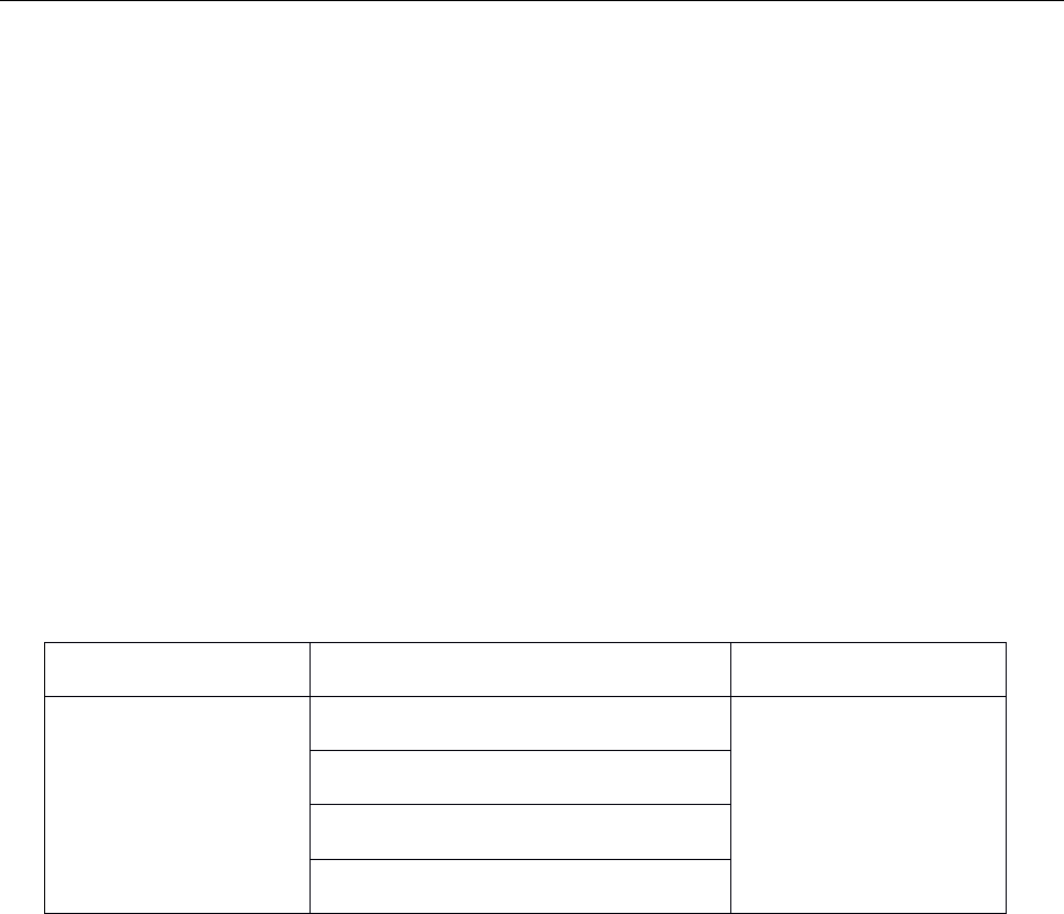
Part 7. Machine Readable Visas 43
if there is a mismatch between a field of the visa MRZ and the corresponding document feature
stored within the seal, then the status is INVALID with sub-indication SEAL_VISA_MISMATCH.
Additional information on the mismatch SHOULD be provided. Otherwise, the visa MRZ validation
should continue.
2. Passport MRZ Validation
If the checksums of the passport MRZ are not compliant with the applicable norm, depending on
the passport type, then the status is INVALID with sub-indication INVALID_PASSPORT_MRZ.
Otherwise, the passport MRZ validation should continue.
3. Passport Link Validation
If any of the fields of the passport MRZ listed as follows do not correspond to their equivalent
feature stored in the digital seal, then the status is INVALID with sub- indication
SEAL_PASSPORT_MISMATCH. The MRZ fields of the passport are: 1) passport number and 2)
passport issuing State. Otherwise, if all fields match, the status of the Visible Digital Seal is VALID.
The generic and visa-specific validation rules cover a comparison of the data stored in the seal against data stored on
the MRZ of the visa and the passport. Furthermore, a manual inspection of those data that are stored in the seal and
printed on the visa, but are not present in the MRZ of the visas, could be conducted.
Table 2. Recommended Trust Levels of the Visa Policy
for Visa specific sub-status indications
Status indication
Sub-status indication
Trust level
INVALID
INVALID_VISA_MRZ
High fraud potential
SEAL_VISA_MISMATCH
INVALID_PASSPORT_MRZ
SEAL_PASSPORT_MISMATCH
10. REFERENCES (NORMATIVE)
Certain provisions of the following international Standards, referenced in this text, constitute provisions of Part 7 of
Doc 9303. Where differences exist between the specifications contained in Part 7 and the referenced Standards, to
accommodate specific construction requirements for machine readable travel documents, including machine readable
visas, the specifications contained herein shall prevail.
ISO/IEC 7810
ISO/IEC 7810:2019, Identification cards — Physical characteristics
ISO 1831
ISO 1831:1980, Printing specifications for optical character recognition
— — — — — — — —
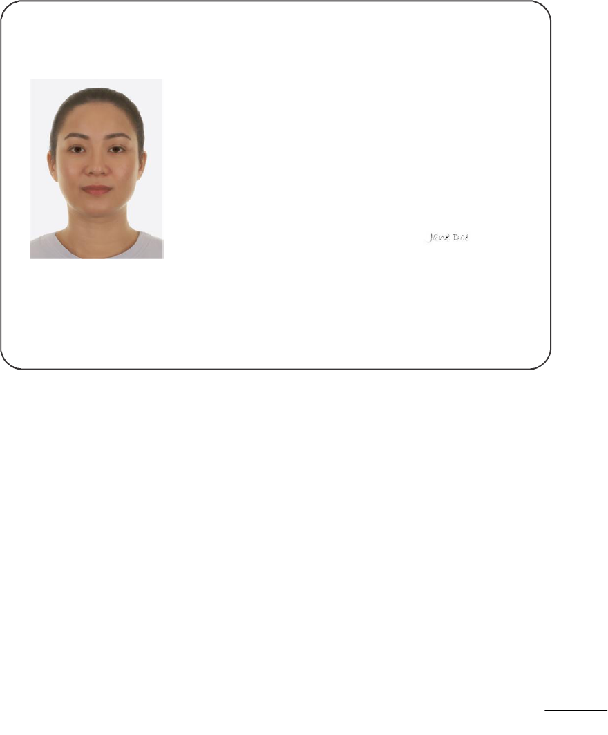
App A-1
Appendix A to Part 7
EXAMPLES OF PERSONALIZED MRVs (INFORMATIVE)
A.1 MRV-A EXAMPLES
Figure A-1. Example illustrates an MRV-A with: Zones I, III, II, IV, V and VII;
a holder with unspecified nationality (i.e. “XXX”).
20/3/24
No. 1
Not to scale
UTOPIA VISA
Place of Issue/Lieu de délivrance
Valid from/Valide partir duà Valid until/Valide jusqu’au
ZENITH
10 DEC 91 /DÉC 10 DEC 96 /DÉC
No. of Entries/ Nombre d’entrées
MULTIPLE
Document No./N° de document
M123889546
Type/Type
BUSINESS MULTIPLE
Surname, Given names/ Nom, Prénoms
ERIKSSON ANNA MARIA
Passport Number/N° de passeport
Sex/Sexe
Date of Birth/
Date de naissance
Nationality/
Nationalité
XXX
12 AUG/AOÛT 74F/F
L8988901C
V<UTOERIKSSON<<ANNA<MARIA<<<<<<<<<<<<<<<<<<<
L8988901C4XXX F96121096ZE184226B<<<<<<7408122
Signature of Issuing officer/
Signature de l’autorité émettrice
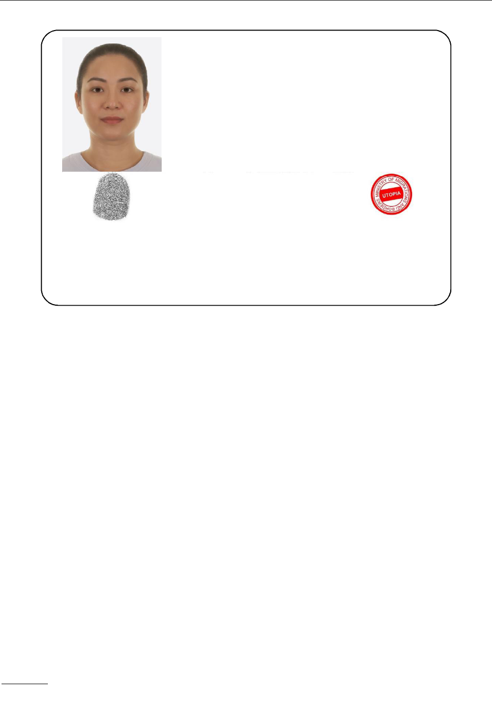
App A-2 Machine Readable Travel Documents
Figure A-2. Example illustrates the same MRV-A as in Figure A-1 but with: Zone V increased
in size to accommodate fingerprint and thus overlaying part of Zone I;
part of Zone II (passport number) overlaying Zone V; and an issuing
office stamp instead of the signature in Zone IV.
20/3/24
No. 1
UTOPIA VISA
Place of Issue/Lieu de délivrance
Valid from/Valide partir duà
Valid until/Valide jusqu’au
ZENITH 10 DEC 91 /DÉC 10 DEC 96 /DÉC
No. of Entries/ Nombre d’entrées Document No./N° de document
MULTIPLE
M123889546
Type/Type
BUSINESS MULTIPLE
Surname, Given names/ Nom, Prénoms
ERIKSSON ANNA MARIA
Sex/Sexe
F/F
Date of Birth/
Date de naissance
12 AUG/AOÛT 74
Nationality/
Nationalité
XXX
V<UTOERIKSSON<<ANNA<MARIA<<<<<<<<<<<<<<<<<<<
L8988901C4XXX F96121096ZE184226B<<<<<<7408122
Not to scale
L8988901C
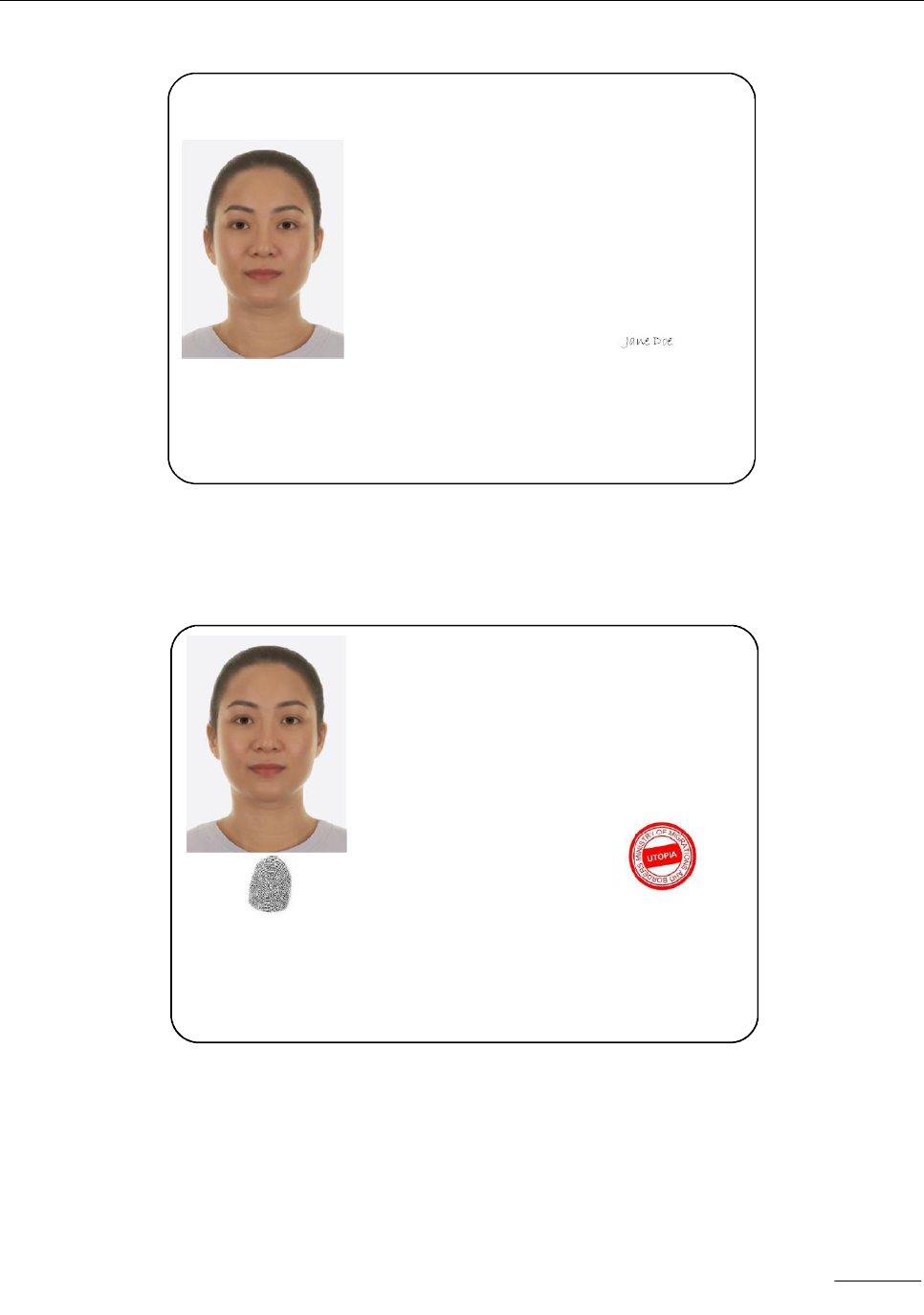
Part 7. Machine Readable Visas App A-3
A.2 MRV-B EXAMPLES
Figure A-3. Example illustrates an MRV-B with: Zones I, III, II, IV, V
and VII; a holder with unspecified nationality (i.e. “XXX”).
Figure A-4. Example illustrates the same MRV-B as in Figure A-3 but with:
Zone V increased in size to accommodate fingerprint and thus overlaying
part of Zone I; part of Zone II (passport number) overlaying Zone V;
and an issuing office stamp instead of the signature in Zone IV.
— — — — — — — —
20/3/24
No. 1
UTOPIA VISA
Place of Issue/Lieu de délivrance
Valid from/Valide partir duà Valid until/Valide jusqu’au
ZENITH
10 DEC 91 /DÉC 10 DEC 96 /DÉC
No. of Entries/ Nombre d’entrées Document No./N° de document
MULTIPLE
M123889546
Type/Type
BUSINESS MULTIPLE
Surname, Given names/ Nom, Prénoms
ERIKSSON ANNA MARIA
L8988901C
Sex/Sexe
F/F
Date of Birth/
Date de naissance
12 AUG/AOÛT 74
Nationality/
Nationalité
XXX
Passport Number/N° de passeport
Signature of Issuing Officer/
signature de l’autorité émettrice
V<UTOERIKSSON<<ANNA<MARIA<<<<<<<<<<<
L8988901C4XXX F9612109<<<<<<<<7408122
Not to scale
UTOPIA VISA
Place of Issue/Lieu de délivrance
Valid from/Valide partir duà Valid until/Valide jusqu’au
ZENITH
10 DEC 91 /DÉC 10 DEC 96 /DÉC
No. of Entries/ Nombre d’entrées Document No./N° de document
MULTIPLE
M123889546
Type/Type
BUSINESS MULTIPLE
Surname, Given names/ Nom, Prénoms
ERIKSSON ANNA MARIA
Sex
F/F
Date of Birth/
Date de naissance
12 AUG/AOÛT 74
Nationality/
Nationalité
XXX
V<UTOERIKSSON<<ANNA<MARIA<<<<<<<<<<<
L8988901C4XXX F9612109<<<<<<<<7408122
Not to scale
/Sexe
L8988901C
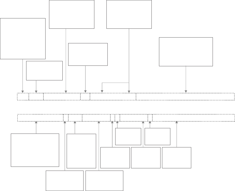
App B-1
Appendix B to Part 7
CONSTRUCTION OF THE MRZ (INFORMATIVE)
B.1 MRV-A MRZ CONSTRUCTION
Figure B-1. MRV-A MRZ construction.
Note 1.— Three-letter codes are given in Doc 9303-3.
Note 2.— Dotted lines indicate data fields; these, together with arrows and comment boxes, are shown for
the reader’s understanding only and are not printed on the document.
Note 3.— Data are inserted into a field beginning at the first character position starting from the left.
Any unused character positions shall be occupied by filler characters (<).
V indicates that the
document is a visa.
One additional character
may be used to further
identify the document at the
discretion of the issuing State.
Primary identifier. Where
there is more than one
component, they shall be
separated by a single filler.
Three-letter code
to indicate the
issuing State
Double filler
characters indicate that
this is the end of
the primary identifier.
Secondary identifier.
Each component is
separated by a single
filler character.
Filler characters. Used to
complete the upper machine
readable line, indicate there
are no other name
components included
Passport or visa number
comprising up to 9
alphanumeric characters.
Unused character
positions occupied
by a filler (<).
Check digit
on the
document number
Nationality of
the holder
represented
by a
-three letter code
Holder’s date of
birth in format
YYMMDD
Check digit on
date of birth
Sex of holder
(M, F or <)
Date of expiry
of the visa
in format
YYMMDD
Check digit on
date of expiry
Optional data at the
discretion of the
issuing State
L898902C<3UTO6908061F9406236ZE184226B<<<<<<<
V<UTOERIKSSON<<ANNA<MARIA<<<<<<<<<<<<<<<<<<<
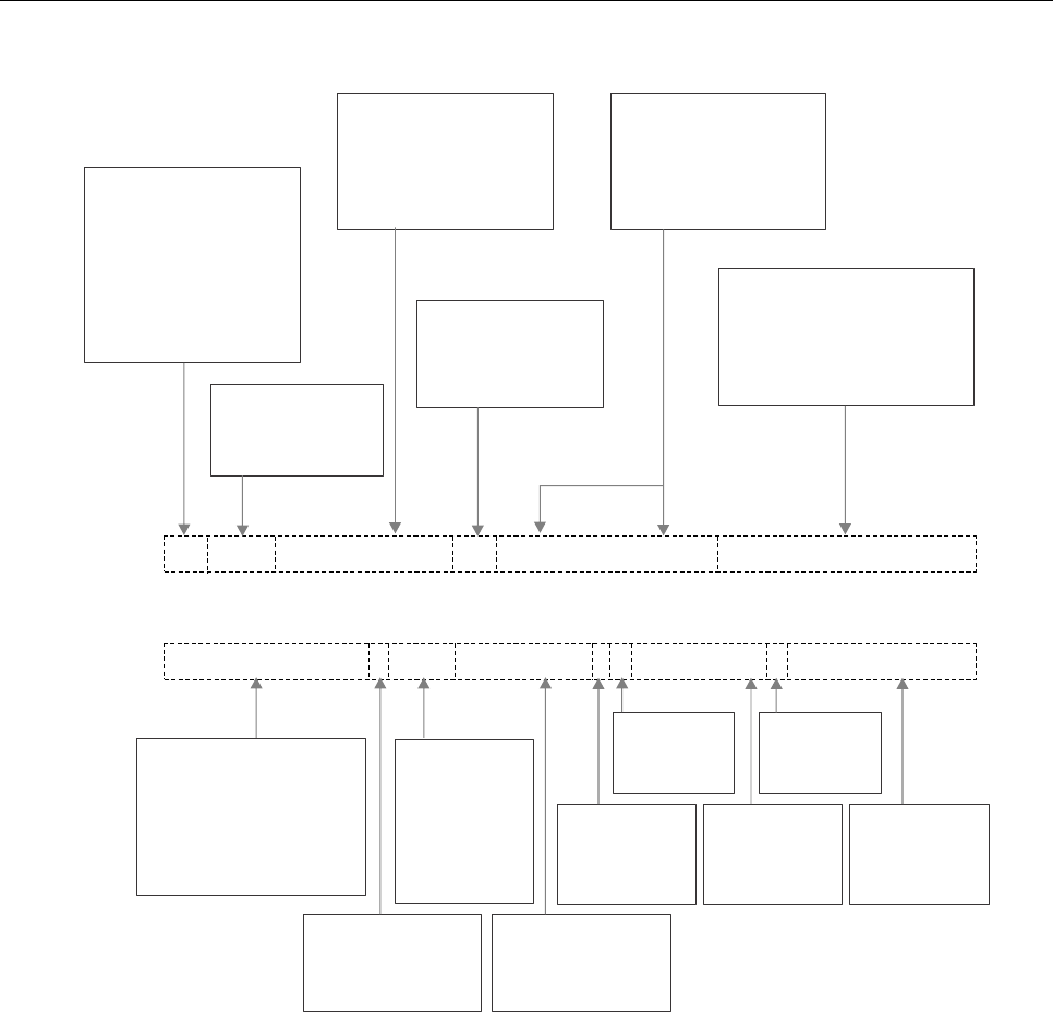
App B-2 Machine Readable Travel Documents
B.2 MRV-B MRZ CONSTRUCTION
Figure B-2. MRV-B MRZ construction
Note 1.— Three-letter codes are given in Doc 9303-3.
Note 2.— Dotted lines indicate data fields; these, together with arrows and comment boxes, are shown for
the reader’s understanding only and are not printed on the document.
Note 3.— Data are inserted into a field beginning at the first character position starting from the left.
Any unused character positions shall be occupied by filler characters (<).
— — — — — — — —
V indicates that the
document is a visa.
One additional character
may be used to further
identify the document at the
discretion of the issuing State.
Primary identifier. Where
there is more than one
component, they shall be
separated by a single filler.
Three-letter code
to indicate the
issuing State
Double filler
characters indicate that
this is the end of
the primary identifier.
Secondary identifier.
Each component is
separated by a single
filler character.
Filler characters. Used to
complete the upper machine
readable line, indicate there
are no other name
components included
Passport or visa number
comprising up to 9
alphanumeric characters.
Unused character
positions occupied
by a filler (<).
Check digit
on the
document number
Nationality of
the holder
represented
by a
-three letter code
Holder’s date of
birth in format
YYMMDD
Check digit on
date of birth
Sex of holder
(M, F or <)
Date of expiry
of the visa
in format
YYMMDD
Check digit on
date of expiry
Optional data at the
discretion of the
issuing State
V<UTOERIKSSON<<ANNA<MARIA<<<<<<<<<<<
L898902C<3UTO6908061F9406236ZE184226
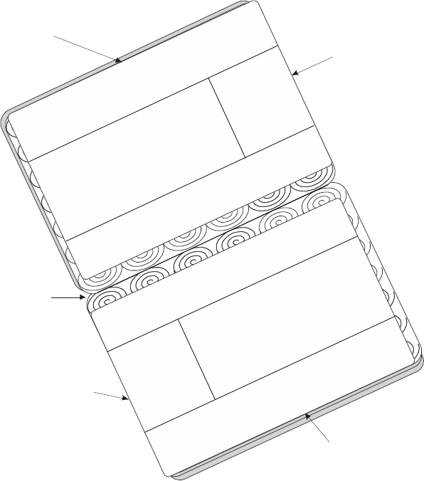
App C-1
Appendix C to Part 7
POSITIONING IN PASSPORT (INFORMATIVE)
C.1 MRV-A POSITIONING
Figure C-1. MRV-A Positioning
Each MRV shall be placed so that:
• the two OCR lines of the MRZ are parallel to the appropriate reference edge of the passport visa
page;
• the leading characters of each OCR line are positioned with respect to the left edge of the passport
visa page;
• the MRZ is immediately adjacent to the appropriate reference edge of the passport visa page; and
• no MRV may be placed on top of another, nor on the reverse of a page that already has an MRV
affixed, nor on the reverse of an MRP data page.
Reference edge of
the passport visa page
M
R
Z
H
e
a
d
e
r
V
i
s
u
a
l
i
n
s
p
e
c
t
i
o
n
z
o
n
e
H
e
a
d
e
r
V
i
s
u
a
l
i
n
s
p
e
c
t
i
o
n
z
o
n
e
Spine of
the passport
Left edge of
the passport visa page
Reference edge of
the passport visa page
Left edge of
the passport visa page
M
R
Z
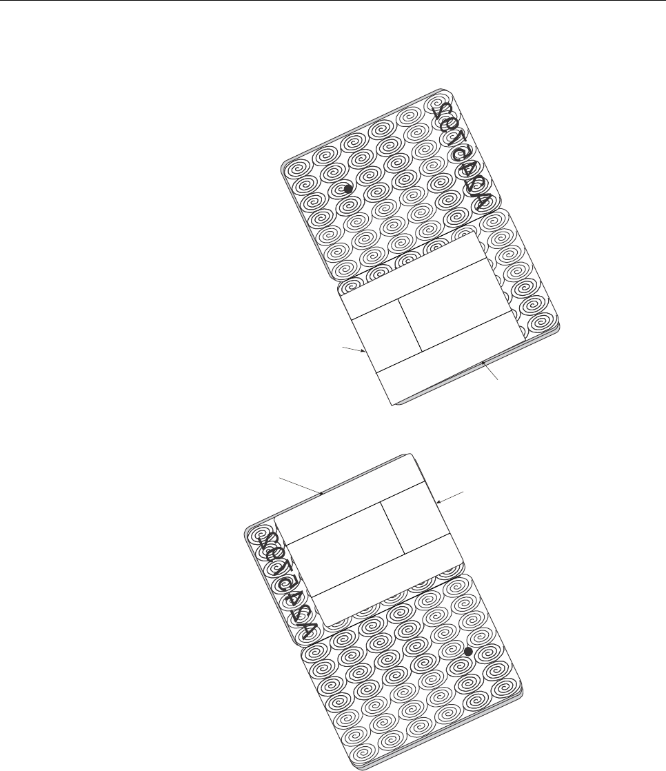
App C-2 Machine Readable Travel Documents
C.2 MRV-B POSITIONING
Figure C-2. MRV-B Positioning
— — — — — — — —
Reference edge of
the passport visa page
Left edge of
the passport visa page
M
R
Z
H
e
a
d
e
r
V
i
s
u
a
l
i
n
s
p
e
c
t
i
o
n
z
o
n
e
A
2
4
5
7
9
2
NOTE: MRV not permitted
on this numbered page
(shall not cover the perforation)
Left edge of
the passport visa page
Reference edge of
the passport visa page
H
e
a
d
e
r
V
i
s
u
a
l
i
n
s
p
e
c
t
i
o
n
z
o
n
e
M
R
Z
A
2
4
5
7
9
2
NOTE: MRV not permitted
on this numbered page
(shall not cover the perforation)
Example 1:
Printed or perforated number at the
top of the passport visa page
Example 2:
Printed or perforated number at the
bottom of the passport visa page
App D-1
Appendix D to Part 7
MATERIALS AND PRODUCTION METHODS (INFORMATIVE)
Note 1.— The following information reflects some past as well as current practices of MRV producers and
is included here for guidance only. It is not an endorsement of any product or method.
Note 2.— It is the responsibility of the issuing State to ensure that the MRV selected for issue is
constructed in such a way that the document will perform satisfactorily for its required life.
Traditionally, visas have taken the form either of a label affixed to a page of the holder’s passport or the application of an
imprint onto the passport page usually with manual infilling for the personalization. Manual infilling is obviously
impractical for machine readable visas where very precise characters for optical recognition are required. There is no
fundamental reason why a visa should not be imprinted onto a passport page using a printer capable of printing OCR-B.
However, an issuing State that elects to do this will find that many passports, which, of course, are issued by other
States, have printed or perforated numbers or other printing on their pages which can absorb the infra-red light used by
the document reader and result in a failure to read at border control. In general, therefore, it is better to use a machine
readable visa in the form of a label affixed to the passport page.
An MRV can have a life limited to a single entry into a country or it can allow multiple entries over the life of the passport
or beyond. The issuing State should ensure that the MRV is appropriately durable for the required life. States should
also ensure that their visas are resistant to fraud. States can achieve considerable protection against these threats
where border control has access to a central database containing the details of the issuance of genuine visas. However
this is not always practicable. The threats are:
• total counterfeiting of the document;
• removal of a visa from one passport and its placement in another;
• alteration of the personal information or validity data.
Substrate. Visas have been produced using either paper or a synthetic polymer as the substrate. The substrate should
have adequate opacity to prevent any printing or perforations on the passport page affecting the machine reading. The
substrate should exhibit no visible fluorescence when irradiated by ultra violet light. Common choices of security features
for paper have included: chemical reactants, iridescent plaquettes, fibres (silk and/or synthetics, visible and/or invisible,
fluorescent and/or non-fluorescent), and security threads. Synthetic polymer substrates may also incorporate some of
these security features. Care must be taken to ensure that any chemical reactants used are unaffected by the adhesive
used to affix the visa. It is desirable that the substrate be damaged by attempts to alter the data on the visa or to remove
it from the passport. The damage may take the form of tearing or distortion.
Inks. Inks that are chemically fugitive, fluorescent, heat sensitive, and optically variable are means of enhancing security
in the MRV.
Printing. Fine line printing, rainbow (split fountain) printing using guilloche patterns, intaglio printing, and incorporation of
concealed images into the design are methods of enhancing both the security and aesthetics of the MRV.

App D-2 Machine Readable Travel Documents
Adhesive. Water-moistenable or pressure-sensitive adhesives have been used to affix visas into passports. The
selected adhesive should achieve and maintain a strong bond even when heated. The adhesive/substrate combination
should be such that the substrate tears or distorts before the adhesive bond fails.
Die cutting. Though the final size and shape of the visa is defined in these specifications, the size is too small for most
types of visa infilling printers. It is therefore normal for an issuing State to procure visas in a sheet form suitable for the
infilling printer with one or more visas contained within the sheet area, the visas being die cut to shape. It is important to
ensure compatibility between the sheets of visas and the printer to ensure that the visas do not become separated from
the carrier sheet in the printer. It is also important to ensure that the edges of the sheet or of the die-cut shape are not
contaminated with adhesive which can build up in the printer and result in misfeeding. Consistency of position of the die-
cut shape relative to the edges of the sheet is important to ensure that the machine readable information is placed within
the ERZ.
Personalization. Most forms of variable image printing, including laser (covered by a laminate), ink jet, dye sublimation
and dot matrix printing have been used in the personalization of visas, with the first three used where a portrait is
required. To minimize the risk of fraudulent removal of the personalization, the selected combination of substrate and
infilling method should achieve a high penetration of the image into the substrate or a strong bond between the material
forming the image and the substrate.
Protecting the personalization. Protective laminate or lacquer layers may be used to secure the data on the visa. Any
laminate material should be firmly bonded to the substrate so that disruption of the substrate or destruction of the
laminate material occurs when attempts are made to remove the laminate.
— — — — — — — —
App E-1
Appendix E to Part 7
WORKED EXAMPLE VISIBLE DIGITAL SEAL
FOR VISA DOCUMENT (INFORMATIVE)
The following example shows a Visible Digital Seal that results from encoding the data shown in Figure E-1. To generate
the signature, ECDSA-256 with the curve brainpoolP256r1 was used. The domain parameters of brainpoolP256r1 and
the private key encoded as Base64 are:
-----BEGIN EC PARAMETERS-----
MIHgAgEBMCwGByqGSM49AQECIQCp+1fboe6pvD5mCpCdg41ybjv2I9UmICggE0gd
H25TdzBEBCB9Wgl1/CwwV+72dTBBev/n+4BVwSbcXGzpSktE8zC12QQgJtxcbOlK
S0TzMLXZu9d8v5WEFilc9+HOa8zcGP+MB7YEQQSL0q65y35XyyxLSC/8gbevud4n
4eO9I8I6RFO9ms4yYlR++DXD2sT9l/hGGhRhHcnCd0UTLe2OVFwdVMcvBGmXAiEA
qftX26Huqbw+ZgqQnYONcYw5eqO1Yab3kB4OgpdIVqcCAQE=
-----END EC PARAMETERS-----
-----BEGIN EC PRIVATE KEY-----
MIGVAgEAMBQGByqGSM49AgEGCSskAwMCCAEBBwR6MHgCAQEEIFurNtlcXTT/OweZ
OPEd4F5QO8v1kn56es1O/XTSSRtDoAsGCSskAwMCCAEBB6FEA0IABAgTKnJDs8zC
nCcQlwgclqcp7vuOuTYw5TZJjpt84c7SXWinidk77znARxXFrTkV0oHAdU7MCFCL
9maH78Yw34g===
-----END EC PRIVATE KEY-----
Encoding input data yields a byte stream, which are both depicted in the image below. Hashing the header and message
with SHA-256 and signing them with the above private key gave the following signature (r,s):
r:
21C6785B027EC4A5BFA6DDE537E8ADFA91BEB1197BED97ADF2FF89E0A344512B
s:
7B0136C44050F117E507BC2A782FFE15F68DDD6818AF5A7BAF21CA7CFC7E83BE
For the sake of completeness, the signature as DER encoded ASN.1:
3044022021C6785B027EC4A5BFA6DDE537E8ADFA91BEB1197BED97ADF2
FF89E0A344512B02207B0136C44050F117E507BC2A782FFE15F68DDD68
18AF5A7BAF21CA7CFC7E83BE
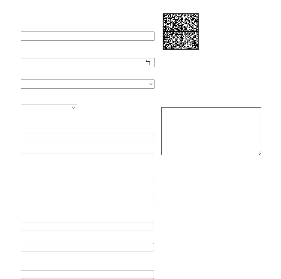
App E-2 Machine Readable Travel Documents
Figure E-1. Example Visible Digital Seal for Visa
Header
UTO
Three-letter country code
Issuing Country
Document Issue Date
Status
SignerCertRef
Encoded RAW data
UTTS025B
Everything worked like charm.a
13.06.2020
Signing Certificate
Select seal type
MRZ 1st line
MRZ 2nd line
Passport Number
Duration of Stay
Number of Entries
Visa Type
Additional Feature
UTTS5b (Utopia)
Visa Document
VCD<<DENT<<ARTHUR<PHILIP<<<<<<<<<<<
1234567XY7GBR5203116M2105253<<<<<<<<
ABC424242
5a0000
2
Format ddmmyy encoded as hex string.
The visa type is encoded as hex string.
Reserved for future use. Encoded as hex string.
Visa Document
DC C5
C6
CA
DA
99C8
5C
54
522C
CE
C6
C3
3C 3C 3C13 13
13 13
13 13
26
26
A6
89
78
37
32
C4
C4
CA
C7
3C 20
39
38
34
3A
33 73
FC
BC
7C 7E
97
F0
D9 D9
DD
5D 5D DF
D95D
B8
4A AF
A7
47744A
A3
2A
AF
AD
DD
4D
A5
AF
FA
40
03 00 00 05 06 59 E9
7E
ED
E5
E0
E8
44
34
E502
01
01 0203
36
68 18
40 07
20
50
03
02
47
5A
21
21
91
91
19
7B
7B
7B
17
B1BE
EB
FF
FF
FE
FE
BF
F1
F2
2F
5A
AD
51
15
2B
5B78
FE F6
F9
8D DD
B3 BE
9F
2F 1A
3A
1E
9F
01
04

Part 7. Machine Readable Visas App E-3
Suppose that seal.bin contains the header and message zone (note that start and length of the signature zone
0xFF and 0x40 are excluded), that the signature is DER encoded in sig.bin, and the above PEM encoded private
key in priv_key.pem. The signature can then be verified with openssl by:
openssl dgst -sha256 -prverify priv_key.pem -signature sig.bin
- sha256 seal.bin
— END —